This article provides a comprehensive guide on the installation of a 300W off-grid micro hydro system for residential use.The system is designed to utilize a water source with a flow rate of 15-30 gallons per minute and a 150-foot drop from the source to the home.
The installation process involves several steps, including constructing a screen box, connecting the silt catchment barrel, installing the penstock, connecting the surge tank and pressure gauge, building the housing for the micro-hydro turbine, adding the Turgo turbine, wiring the system, and installing other essential electrical components.
STEP 1 : BUILDING A SCREEN BOX
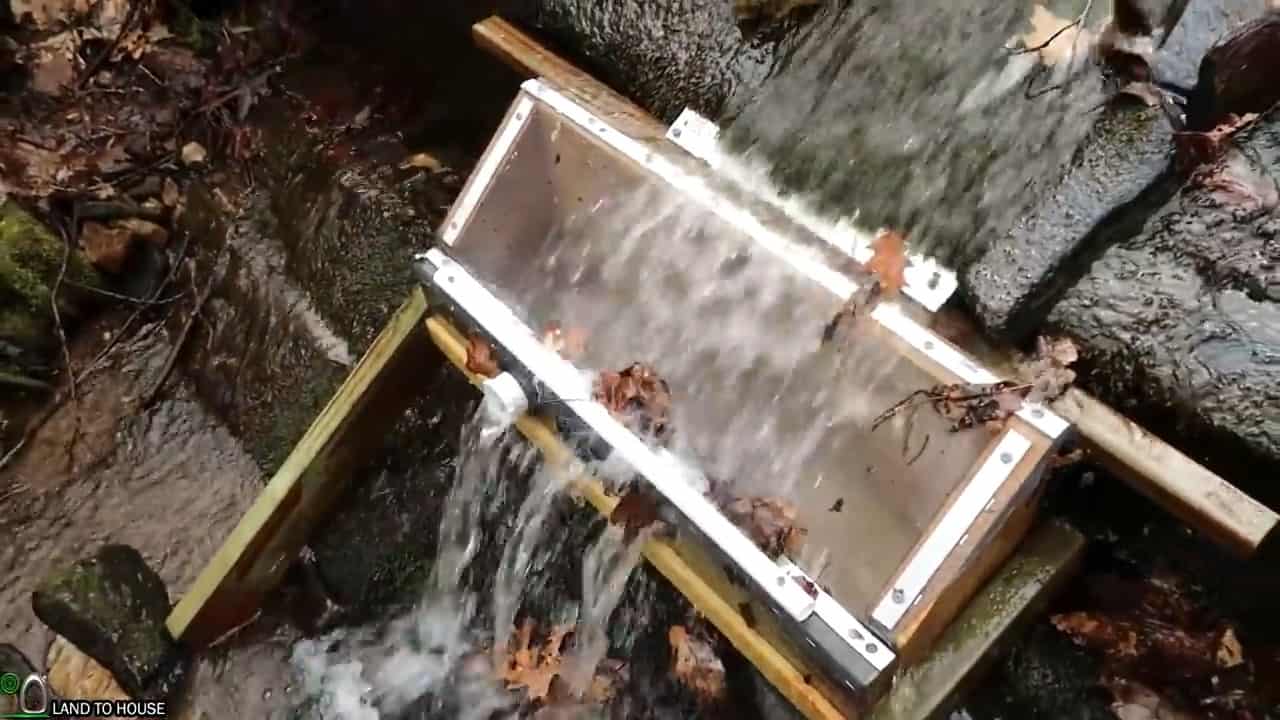
The initial step in setting up a micro hydro system for residential use involves constructing an intake angled screen box to facilitate the flow of water from the source.
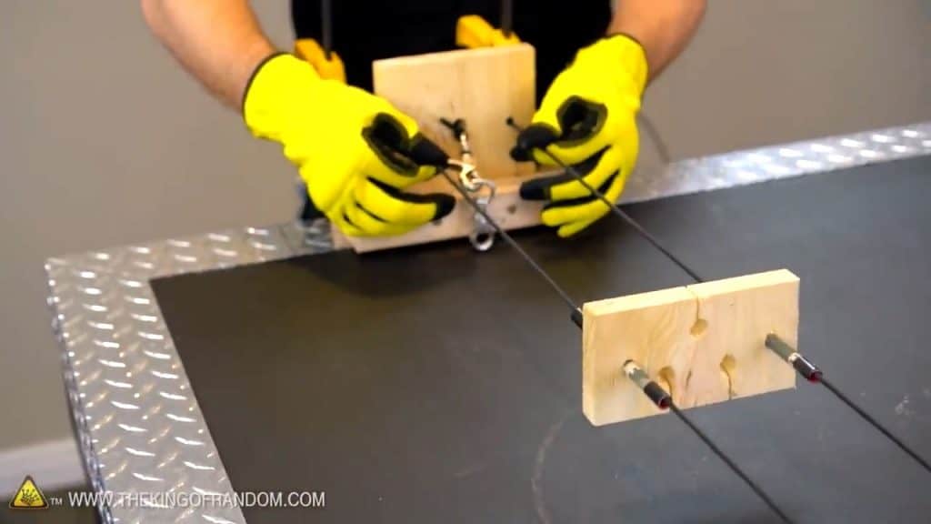
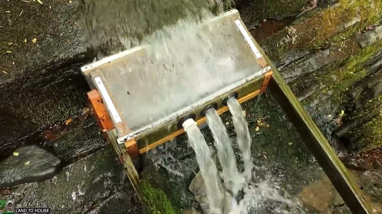
This intake screen box is designed to prevent leaves, sticks, and other debris from clogging the system. The screen box is made of a treated lumber consisting of a 24-inch 2X10, 2X4, and a 2X8 angled piece.
We add 3 one and quarter inch attachment points on the lower side of the box for the HDPE poly pipes.
The box is secured using exterior screws on the outside and inner tubes on the seam to prevent leaks.
The box is secured using exterior screws on the outside and inner tubes on the seam to prevent any leaks.
Additionally, the box is equipped with three attachment points measuring one and a quarter inches on the lower side for the HDPE poly pipes, which will channel the water to the silt catchment barrel.
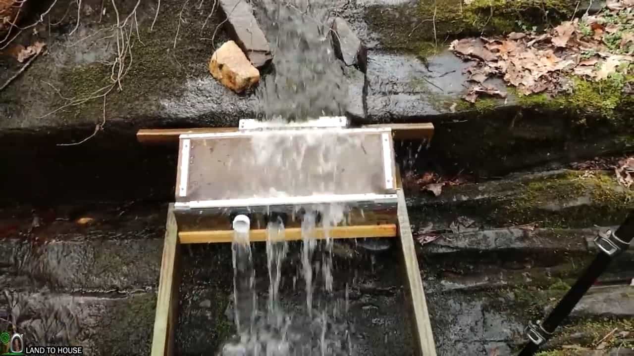
Once completed, the screen box is installed on the creek with the help of three and a half inch concrete anchors and two boards screwed on both sides to provide support.
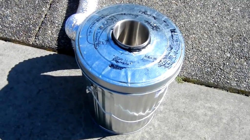
STEP 2 : CONNECTING THE SILT CATCHMENT BARREL
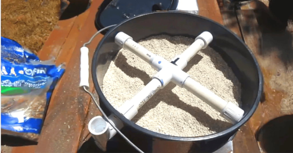
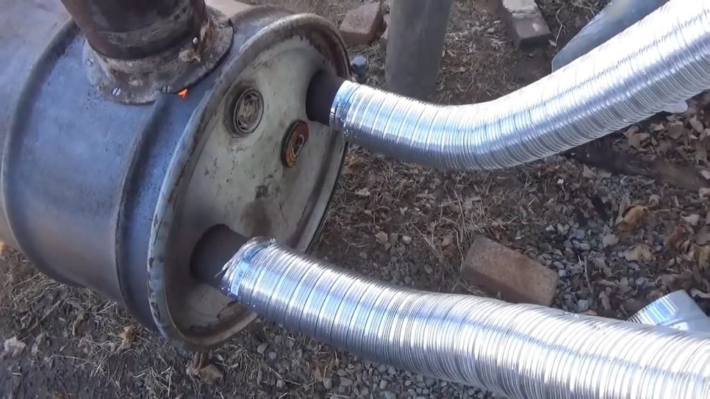
The next step is to connect the outlet poly pipes from the intake angled screen box to a 55-gallon plastic barrel. This barrel is designed to act as a silt catchment and prevent any debris or sediment from entering the micro hydro system.
The three outlet pipes are connected to the top of the barrel using uniseal rubber gaskets, which ensure a tight and leak-proof connection. To facilitate the flow of water to the turbine, a 2-inch pipe is installed midway on the tank for the penstock.
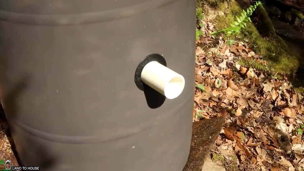

An overflow pipe is also installed near the top of the tank to allow any excess water to flow out of the system, preventing any damage to the micro hydro turbine.
At the bottom of the barrel, a three-inch cleanout pipe is installed to enable easy removal of any silt or debris that may accumulate over time.
This cleanout pipe can be unscrewed for maintenance purposes and re-attached securely to ensure that the system continues to function smoothly.

STEP 3 : INSTALLING THE PENSTOKE
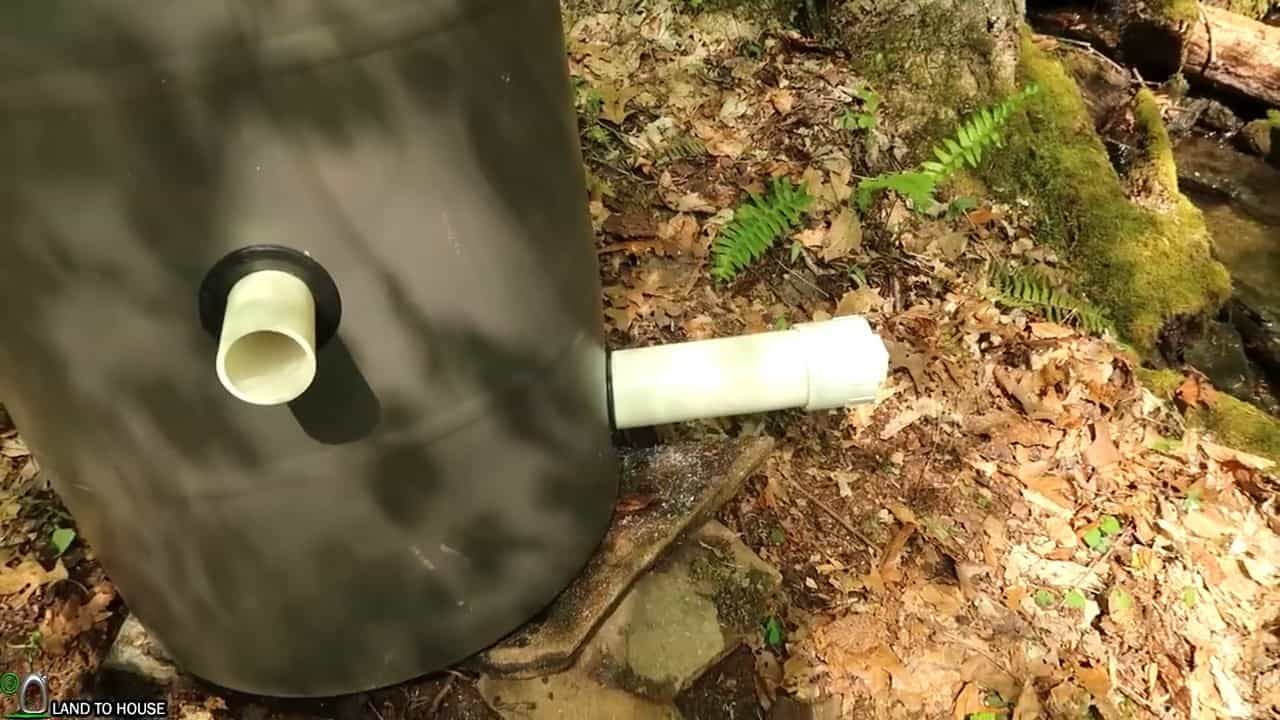
The next crucial step in the installation of a micro hydro system involves setting up the penstock, which is responsible for transporting water from the silt catchment barrel to the micro hydro turbine.
In this particular project, a 100PSI 1100ft 2-inch poly pipe has been selected as the penstock. The poly pipe provides the required strength and durability to withstand the high water pressure and ensure a reliable and continuous flow of water to the turbine.
To connect the penstock to the silt catchment barrel, a threaded adapter is glued to the outlet of the barrel. This adapter provides a secure connection and ensures that there is no water leakage from the joint.
A two-inch full port shutoff ball valve is then connected to the adapter, followed by another threaded adapter and a pipe. This setup provides easy control over the water flow to the turbine and allows for quick shut-off during maintenance or repairs.
The penstock poly pipe is attached to this setup using barb fittings with hose clamps. The barb fittings ensure a tight and leak-proof connection, while the hose clamps provide an additional layer of security against any accidental detachment of the penstock pipe.
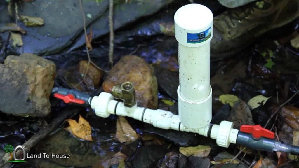
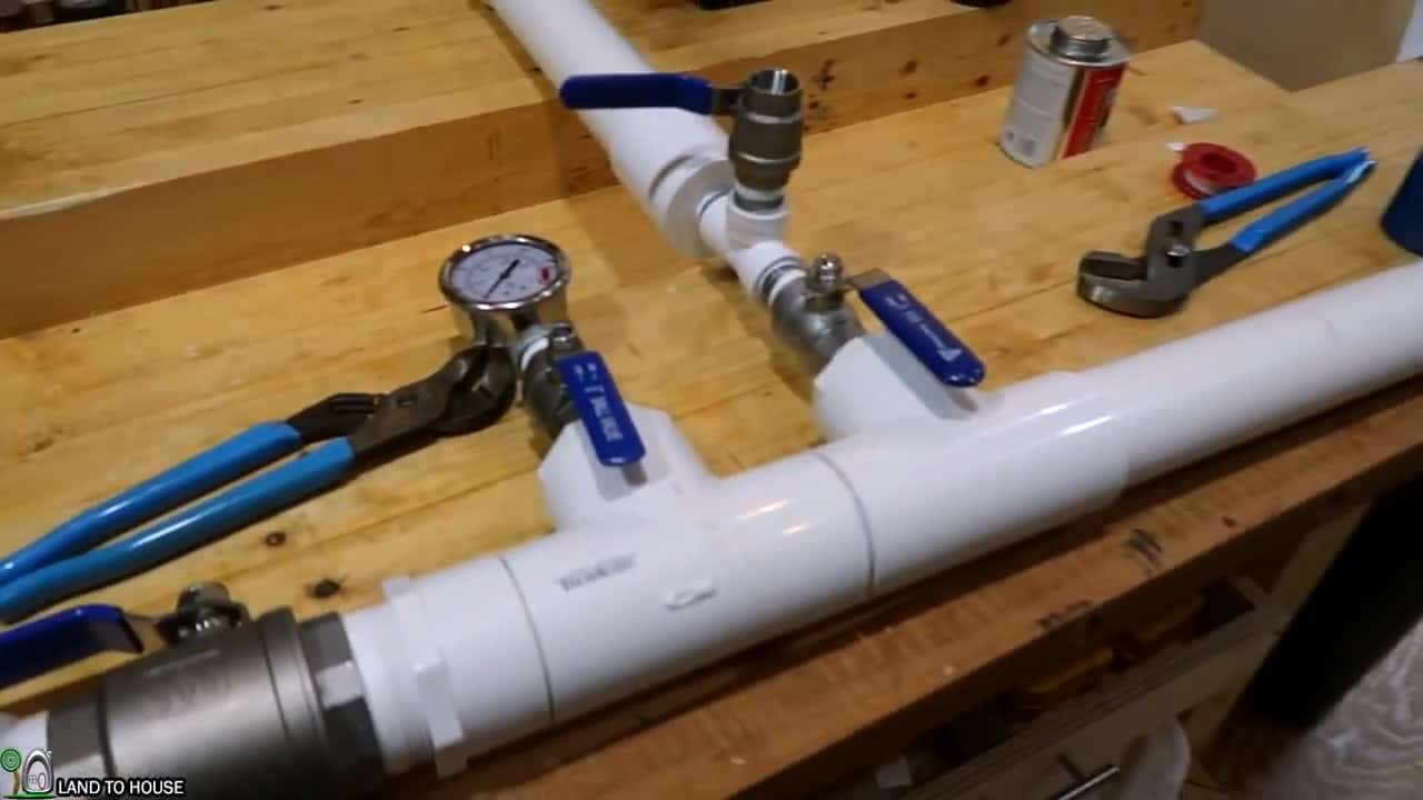
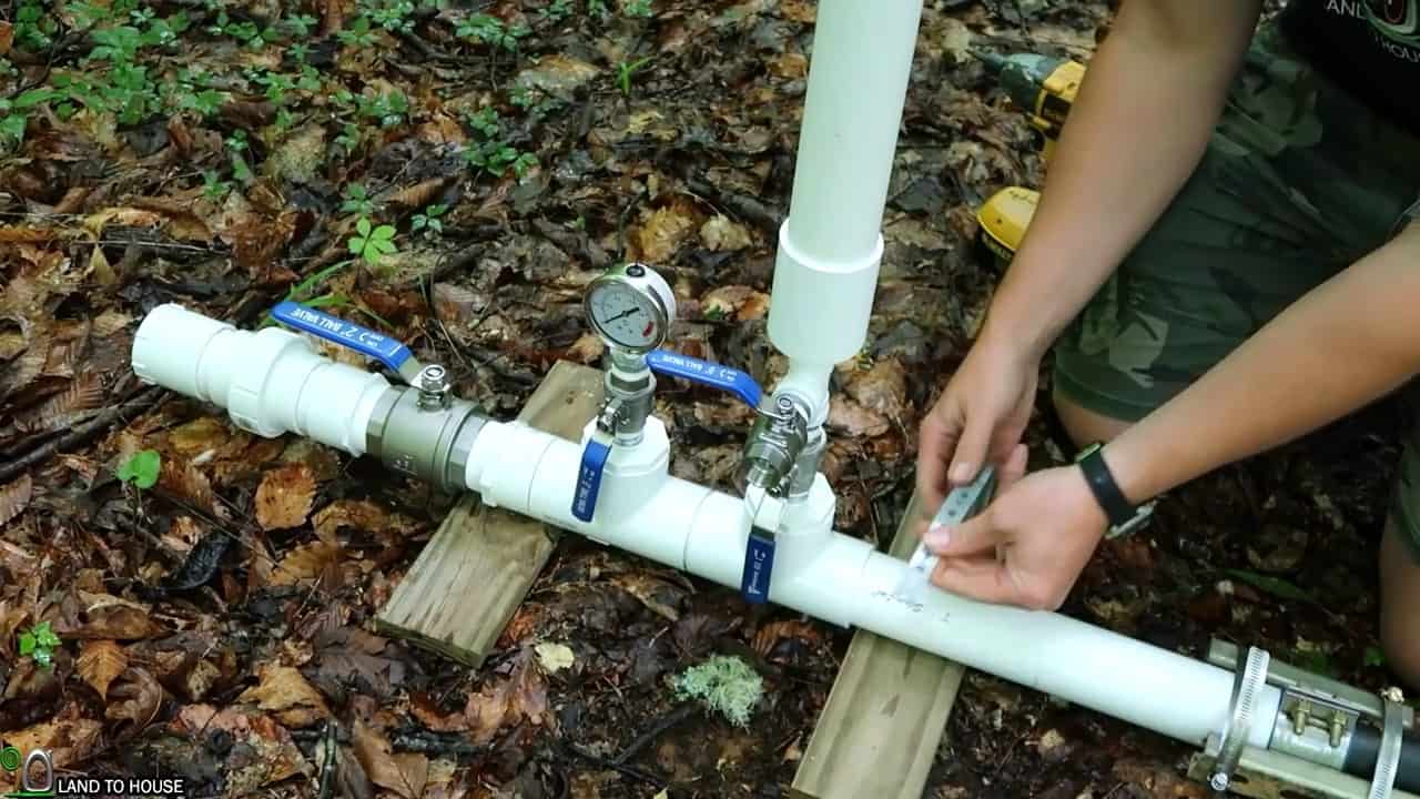
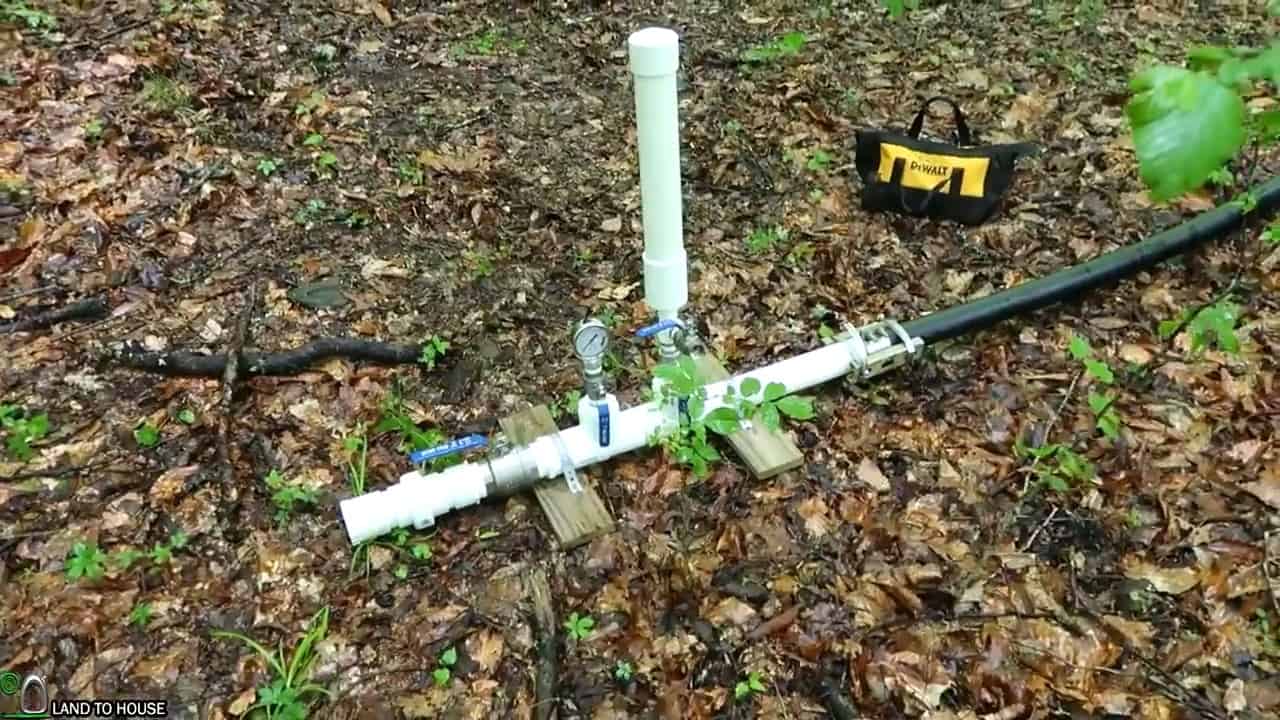
STEP 4 : CONNECTING SURGE TANK AND PRESSURE GAUGE
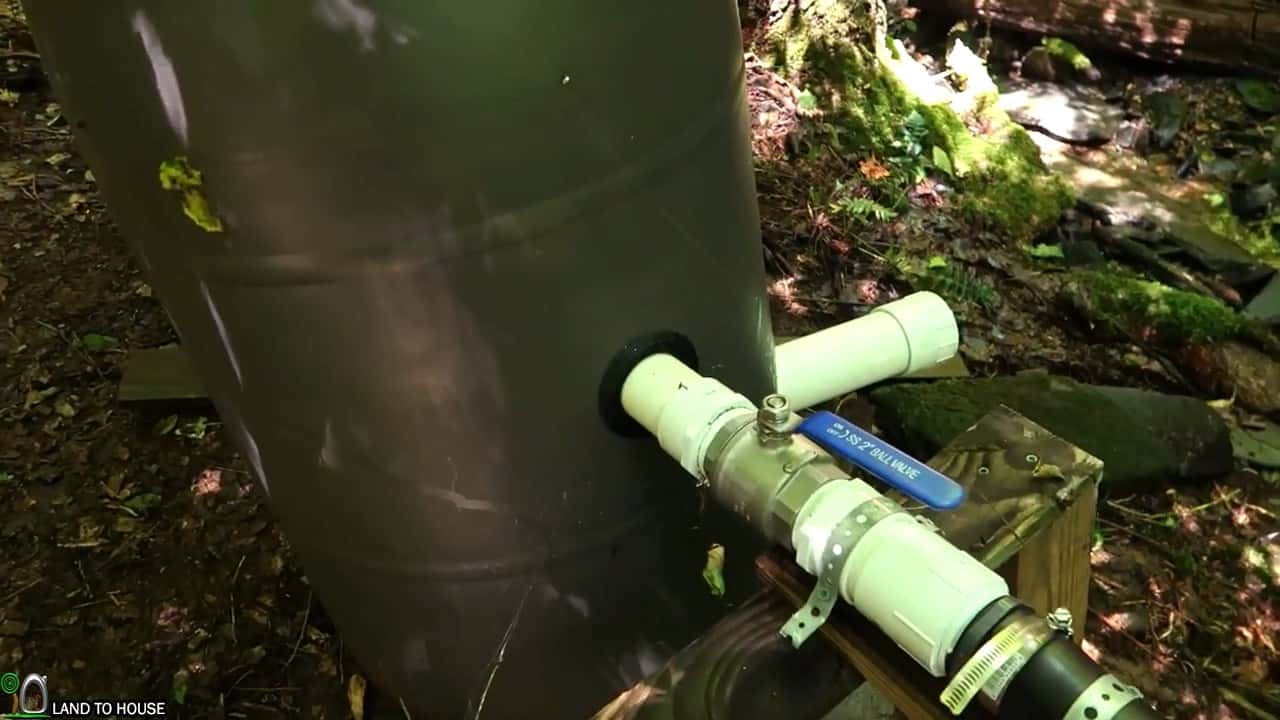
In the next phase of the installation process, the pressure gauge and surge tank are mounted to the penstock pipe. This step is crucial to ensure that the micro-hydro system runs smoothly and efficiently.
Water flows down from the intake through the poly pipe and into a separate PVC pipe that is equipped with a pressure gauge, surge tank, two-inch closing ball valve, and a union to detach the turbine from the pipe.
The pressure gauge allows for real-time monitoring of the water pressure and flow rate, enabling you to assess the performance of the micro-hydro system.
The surge tank acts as a standpipe that minimizes the impact of water hammer, a phenomenon where sudden changes in water flow can damage the pipes.
The surge tank absorbs any sudden surge or pressure spikes that could occur when the main shut-off valve is abruptly closed, protecting the system from damage and ensuring smooth operation.
The two-inch poly pipe emerging from the silt catchment barrel is attached to the two-inch PVC surge tank and pressure gauge.
This connection is essential as it creates a cushioning effect that can absorb some of the surge when the main shut-off valve is abruptly shut.
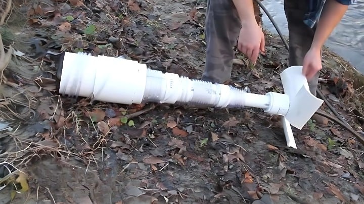
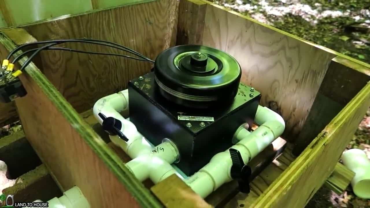
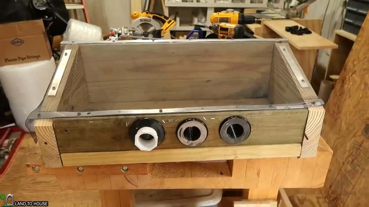
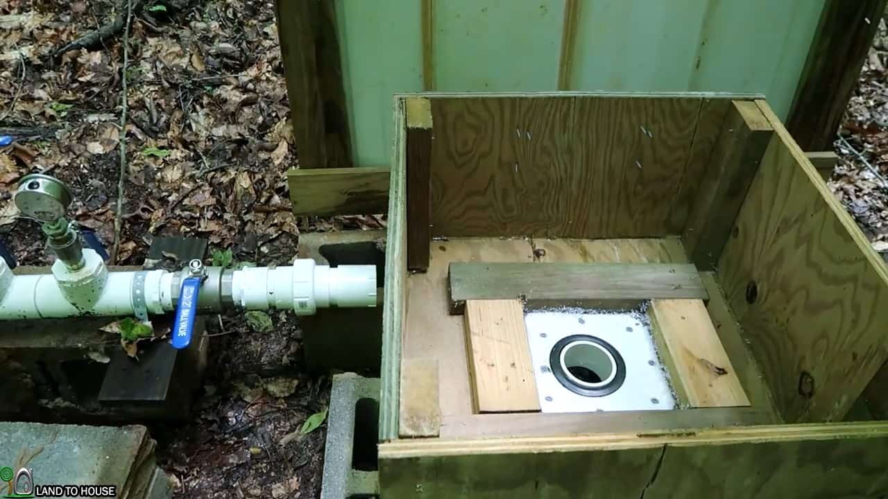
STEP 5 : MICRO HYDRO TURBINE HOUSING
The subsequent step involves constructing a housing for the micro-hydro turbine, which should have a lid that opens up and a drain field pipe that goes out back to the creek.
This housing will be made of three-quarter-inch plywood that is 2 feet wide and 2 feet long and one foot tall, and it will be designed to fit the turbine in the center.
The turbine will be supported by 2×4 scrap wood and a bucket lid piece, ensuring that it is stable and secure. The exit pipe will be 3 inches in diameter and will come out of the housing, going down through the middle to prevent water from accumulating underneath the turbine.
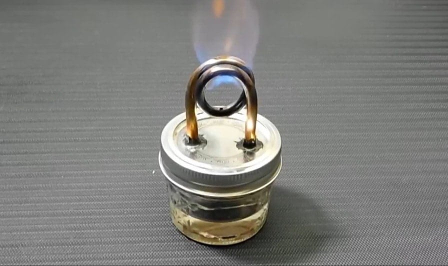
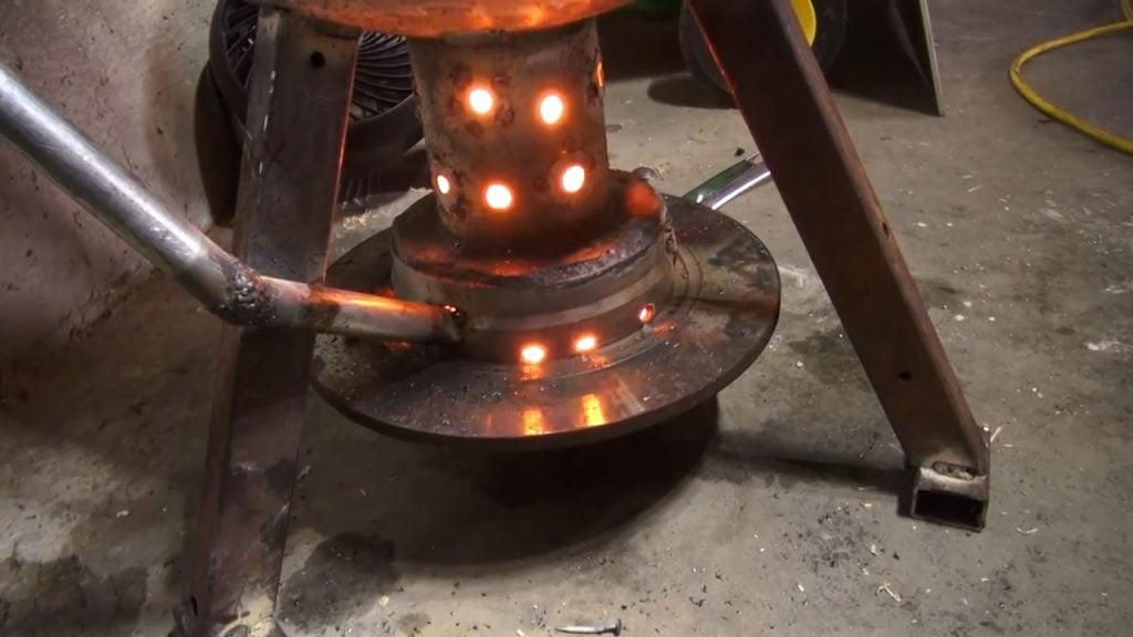
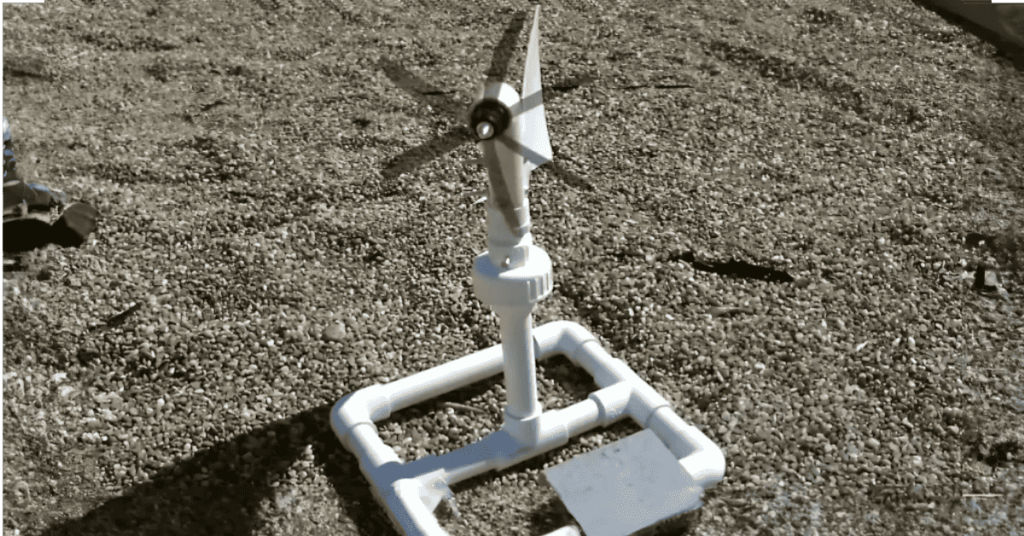
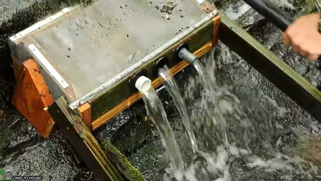
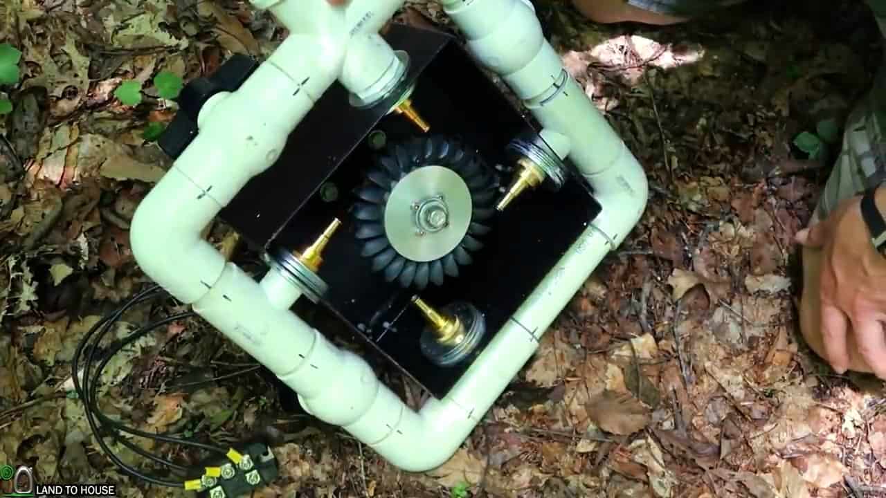
STEP 6 : ADDING THE TURGO TURBINE
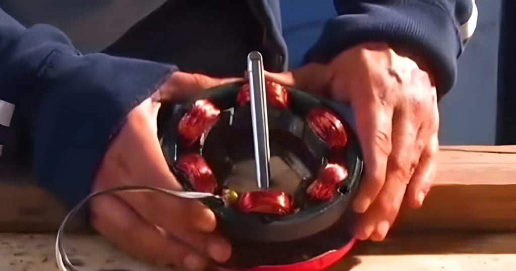
The Micro Hydro Turgo Turbine is a custom-built device designed to match the specific head pressure and flow rate of the water source.
The device is equipped with three ball valves and four quarter-inch jet nozzles coming out of them. These ball valves are designed to be separately turned off when there is not enough water, thus avoiding damage to the turbine.
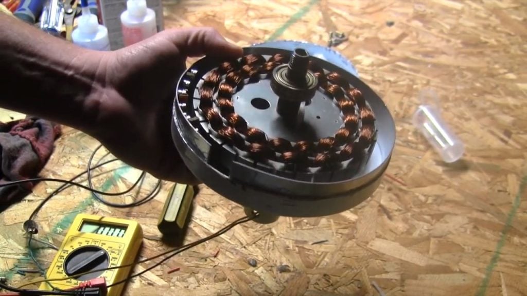
The Turgo Turbine is wired up to be a three-phase system. The water coming out of the penstock hits jet nozzles that turn the Pelton wheel, which is connected to a 3-phase AC motor.
This setup ensures maximum efficiency in the energy conversion process.
STEP 7 : WIRING THE SYSTEM
To connect the turbine to our house, we use a 10/3 underground feeder wire, which is specifically designed to handle the electrical load generated by the micro-hydro turbine.
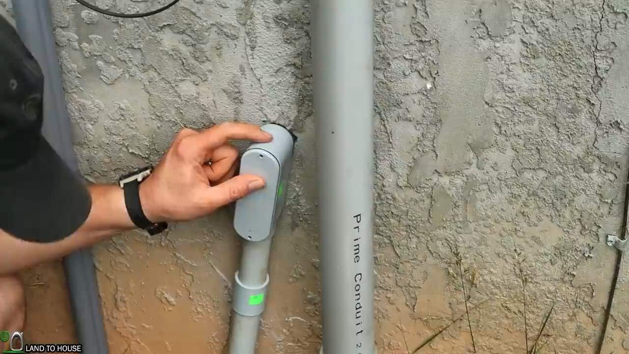
To ensure the wire is protected from damage and the elements, it is enclosed in a one-inch conduit pipe, which acts as a protective shield.
The conduit pipe is first assembled using adhesive glue to ensure it is tightly sealed and secure. To easily pull the wire through the conduit, a vacuum is used to create suction that pulls a string through the entire length of the conduit. The wire is then tied to the string and pulled through the conduit with ease.
Once the wire is through the conduit, it is routed into the house through a PVC conduit body, which is a specially designed connector that provides a secure and waterproof seal between the conduit and the house wiring.

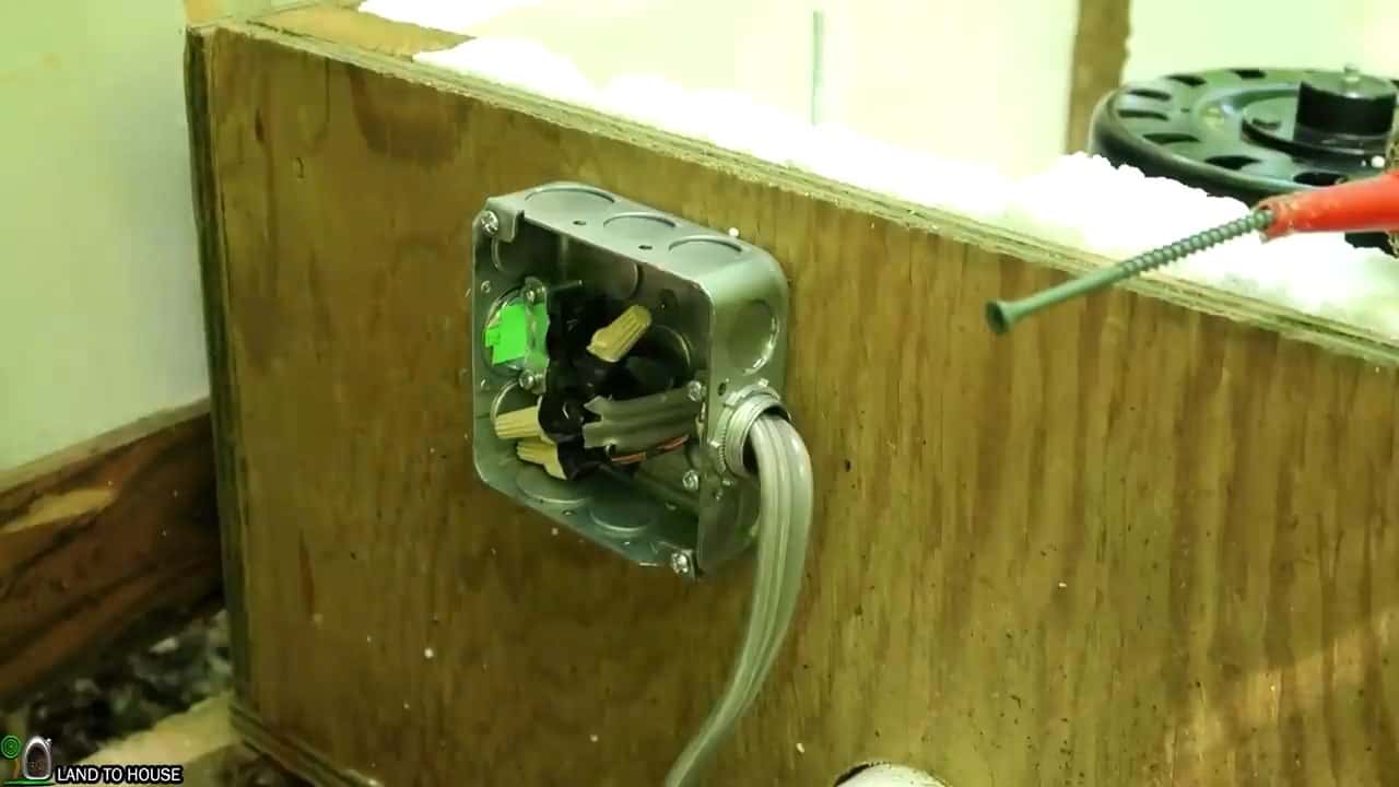
Next, we proceed to install a junction box on the housing of the turbine. This junction box connects the output wires of the three-phase turbine to the 10/3 UG feeder wires that run from the house. Inside the house, we connect a rectifier to the three legs of the three-phase coming from the turbine.
This is an important step as it converts the AC generated by the turbine into DC power that can be used by the home’s electrical system.
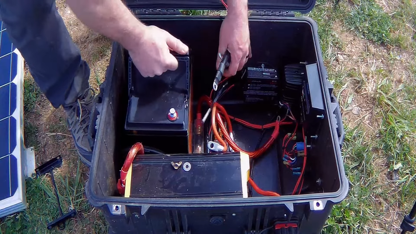
STEP 8 : INSTALLING OTHER ELECTRICAL COMPONENTS
In order to transform the generated DC power from the micro-hydro system into useable AC power for household appliances, several electrical devices need to be installed.
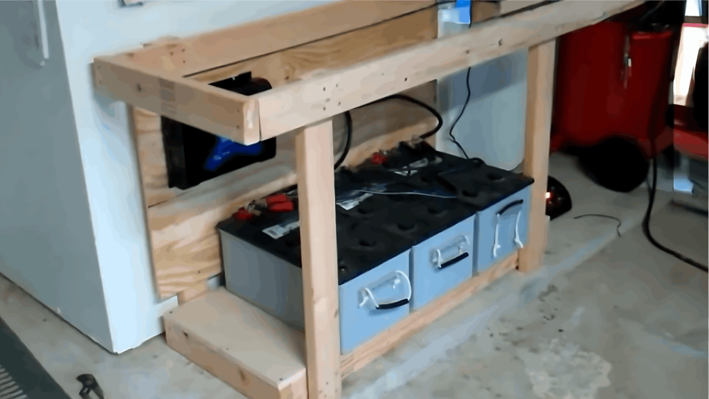
These include the MPPT (Maximum Power Point Tracking) Charge Controller, Grid Tie limiter Inverter, breaker box, disconnect switches, and batteries. To organize and secure these components, they are mounted on a 2 X 2 foot, three-inch plywood board.
To ensure proper heat dissipation and prevent damage to the electrical components, it is important to take measures to mitigate excess heat.
For this reason, a piece of sheet metal can be placed over the plywood board to act as a heat sink. This will help to regulate the temperature of the electrical components and ensure optimal performance.
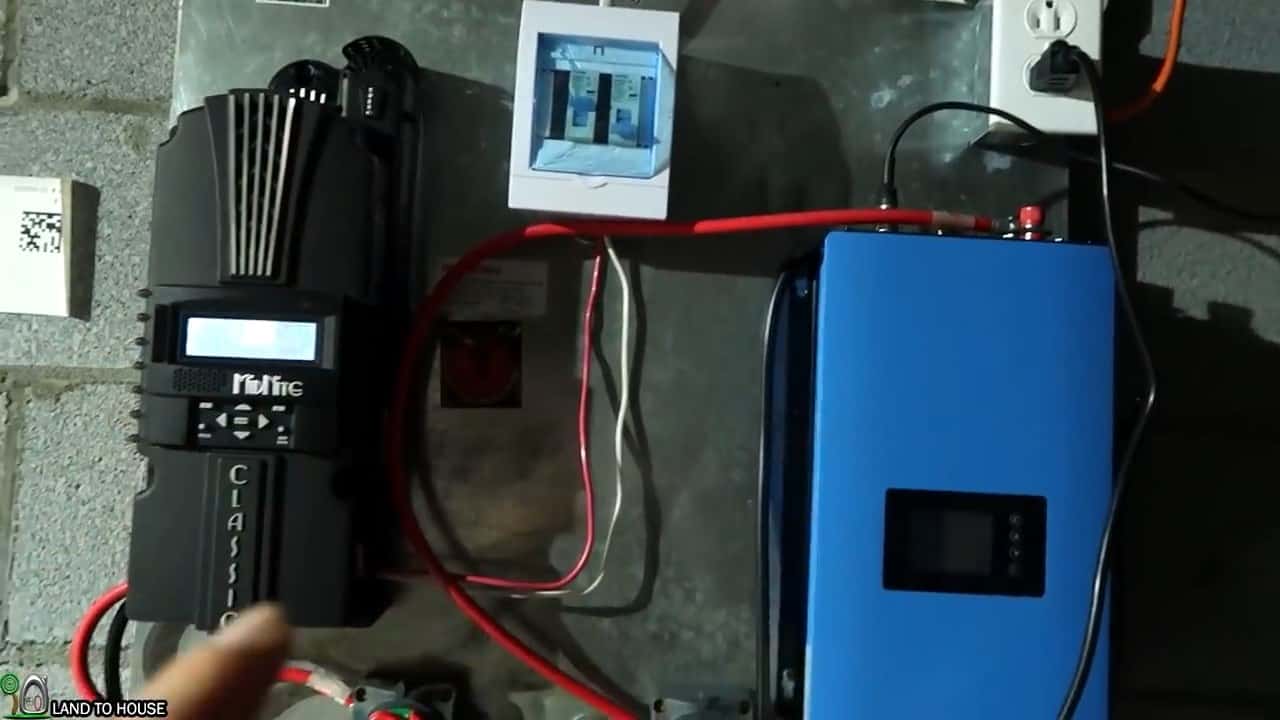
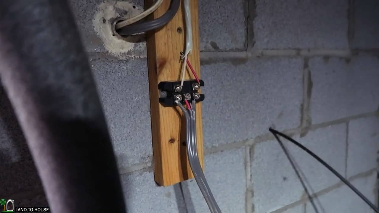
After the three-phase output wires from the rectifier are connected to the breaker box, the red wire is then connected from the breaker box to the positive terminal of the MPPT (Maximum Power Point Tracking) charge controller.
The MPPT charge controller is an essential component of the micro-hydro system, as it optimizes the power output of the turbine by ensuring that it operates at the maximum power point (MPP). This helps to maximize the efficiency of the system.
The negative white wire from the rectifier is directly connected to the negative terminal of the MPPT charge controller.
This completes the circuit between the turbine and the charge controller, which regulates the flow of current from the turbine to the batteries.
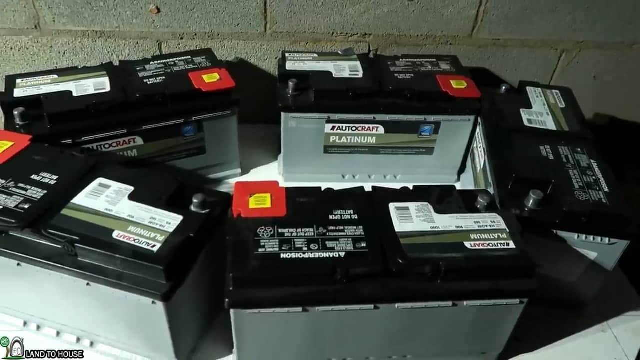
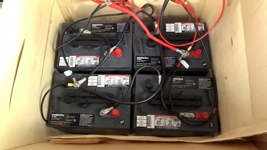
STEP 8 : CONNECTING THE BATTERIES AND COMPLETING THE WIRING
In this step, we will connect the five 12V AGM batteries in series using four gauge cables. This will increase the voltage to 60V, which is necessary for proper functioning of the system.
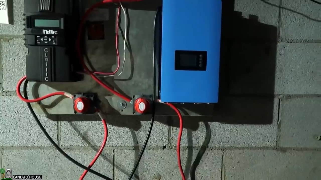
Once the batteries are properly connected, we will connect the positive terminals to the MPPT charge controller and the grid tie limiter inverter using DC switches.
These switches will allow us to isolate and disconnect the components individually for maintenance purposes.
After connecting the positives, we will then connect the negatives of the batteries to the negatives of both the charge controller and inverter respectively.
This will complete the DC circuit of the system. The MPPT charge controller will monitor the voltage and current of the batteries and regulate the charging process to ensure that the batteries are not overcharged or undercharged.
The grid tie limiter inverter will convert the DC power from the batteries to AC power that can be used in our home. The inverter is further connected to the receptacle from where it goes straight to the main supply.
We will also install DC and AC disconnect switches for safety purposes. These switches will allow us to easily disconnect the system in case of an emergency or maintenance requirements.
Image Credits : Land to House