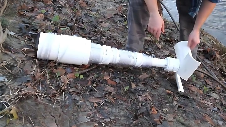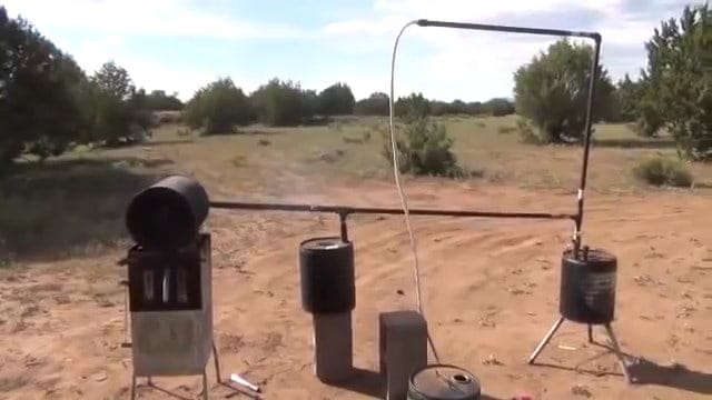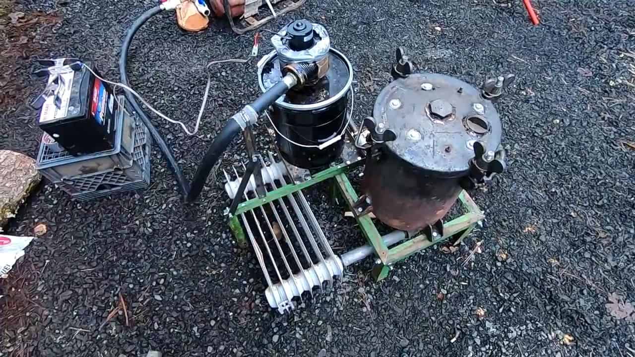
This project entails the construction of a cross-flow wood gasifier capable of producing alternative fuel to power internal combustion engines such as cars and generators.
Organic materials such as wood scraps, paper, or coal may be used to fuel the gasifier, with the unit built using only an angle grinder, a hand drill, and commonly available parts.
The gasification process employed by these devices harnesses the inherent energy within organic biomass. This means that any natural material that has the ability to burn, such as wood scraps, coal, or even paper, can be used.
The process entails subjecting the organic material to intense heat, causing it to break down into its basic elements through pyrolysis.
The result of this process is the production of syngas, also known as wood gas, which can be used as a fuel source for engines.
It’s important to note that the gasification process occurs within an oxygen-deprived environment. This means that the biomass is burned in the absence of oxygen, creating a chemical reaction that converts it into syngas.
This reaction is sustained by providing just enough oxygen to prevent the gases produced by the heat from igniting the surrounding material.
This controlled process ensures the safe and efficient production of wood gas, which can be used as an alternative fuel source.
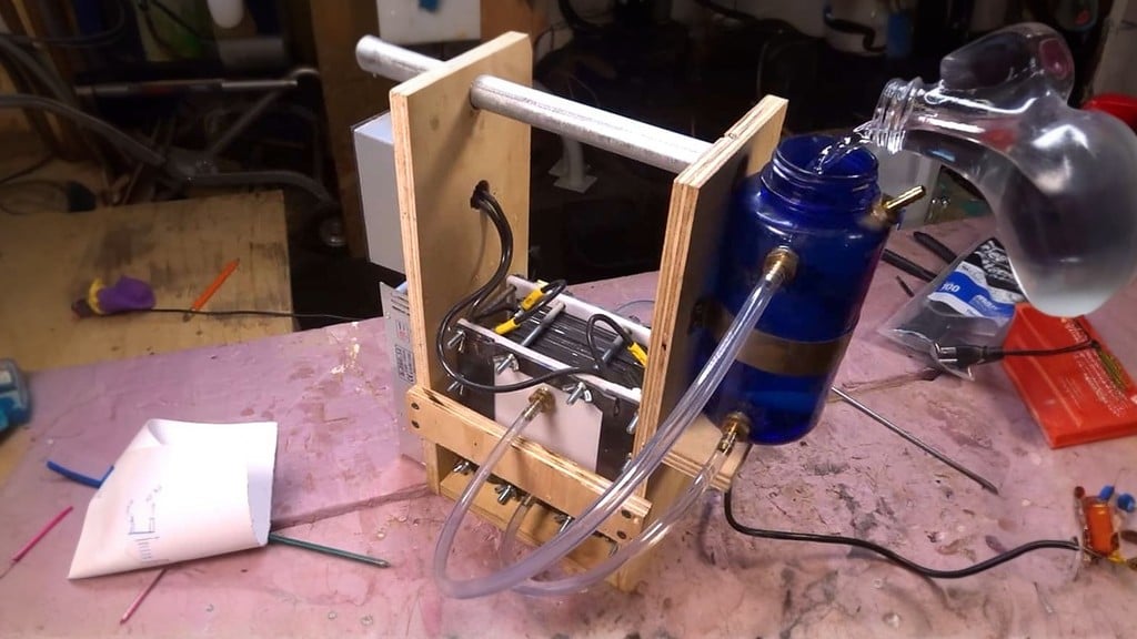
During the gasification process, the resulting gases that are produced contain water vapor from the moisture content in the wood, as well as tar and creosote.
In order to use the gas as a clean fuel source for engines, it is essential to filter it to remove any impurities.
The primary concern in this step is to cool down the gas. To achieve this, the unfiltered gas coming from the pressure pot is connected to a radiator.
The radiator acts as a condensate catcher, allowing the tar and steam to condense back into their liquid form. As the gas passes through the radiator, most of the heat is removed, and it becomes cooler.
The gas is then directed into a bucket filled with sawdust, which acts as a filter medium. The sawdust traps any remaining particulates and removes more tar from the gas.
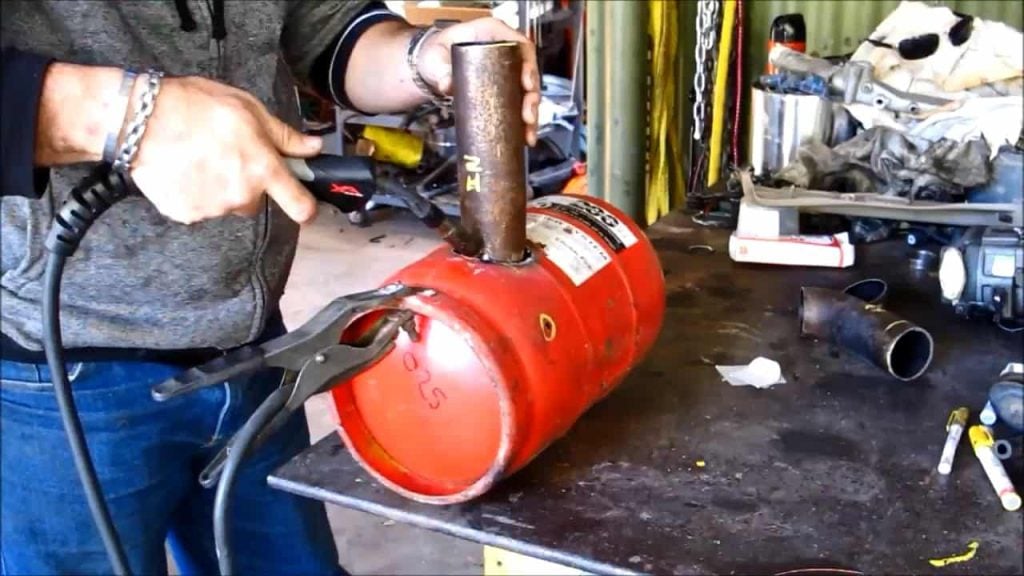
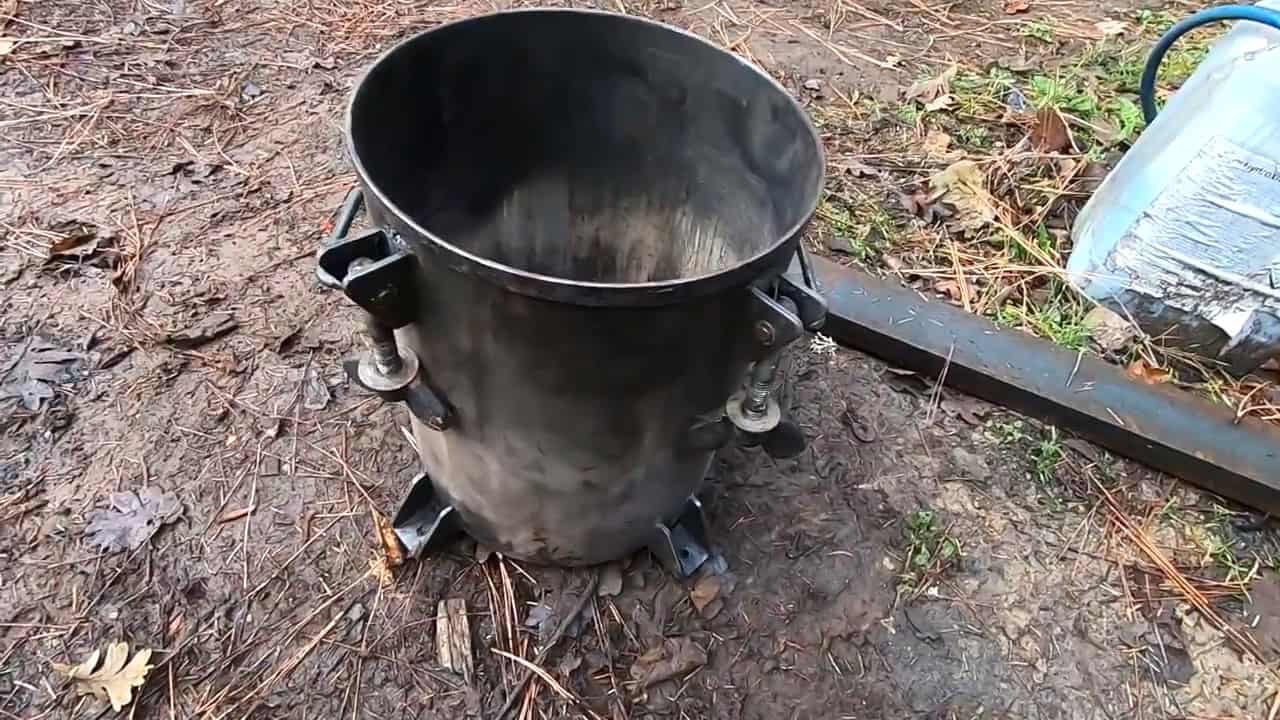
STEP 1 : PREPARING THE REACTOR UNIT
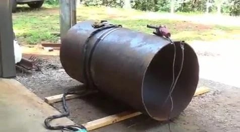
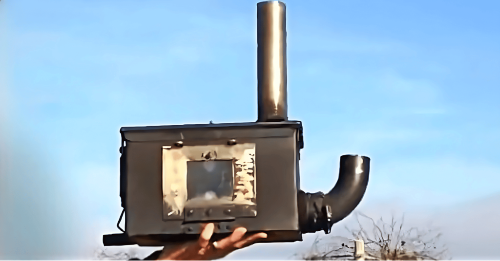
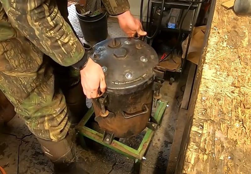
The reactor unit that houses the gasification process is constructed from an old 5-gallon painting pressure pot. The initial step in building the gasifier is to thoroughly clean the pressure pot to remove any old residue and paint. This is achieved by burning out the interior of the pot using intense heat.
It is important to ensure that all traces of paint, debris, and other contaminants are removed from the pressure pot. This is because any leftover material can interfere with the gasification process and compromise the efficiency of the unit.
Once the pressure pot has been thoroughly cleaned, the interior container must also be burned out to remove any remaining contaminants.
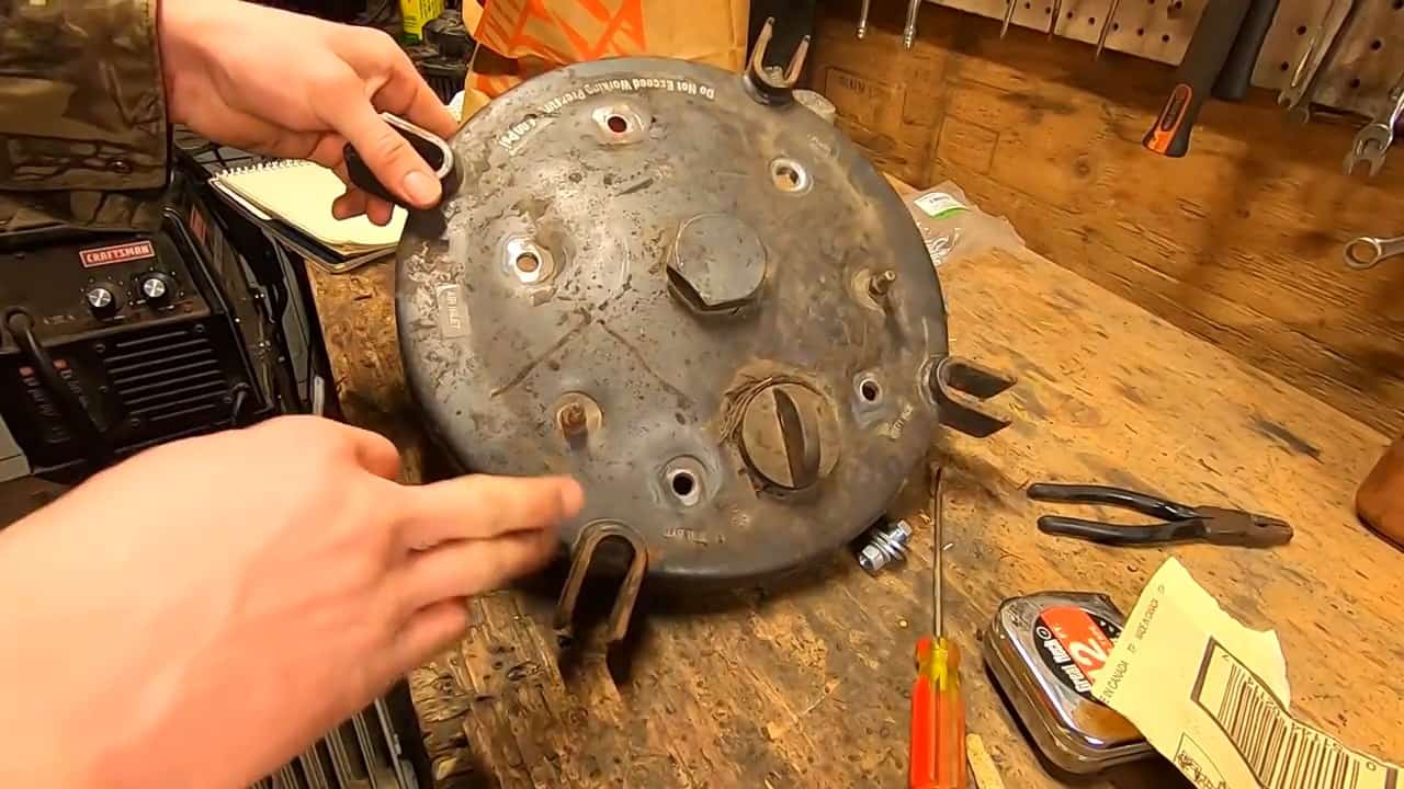
To ensure the safety and efficiency of the gasifier, it is important to ensure that the lid of the pressure pot is properly sealed.
This involves removing any components that may interfere with the gasification process and sealing any openings in the lid.
Firstly, it is important to check that everything on the lid of the pressure pot is removed. This includes any handles or other fixtures that may interfere with the gasification process.
Once these components have been removed, all openings in the lid should be sealed off with a plug or bolt to prevent any gas from escaping.
Additionally, the rubber gasket on the backside of the lid should be removed. This is because the gasket may break down and release harmful chemicals into the gas produced during the gasification process.
Finally, any holes on the surface of the lid should be covered with three eighth-inch bolts. This is done to ensure that the lid is completely sealed and that no gas is able to escape.
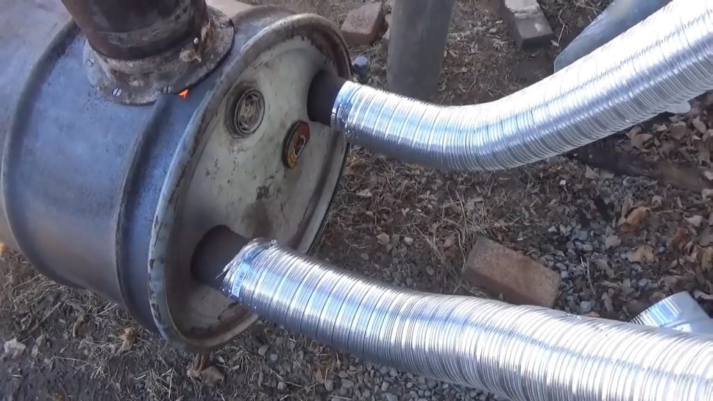
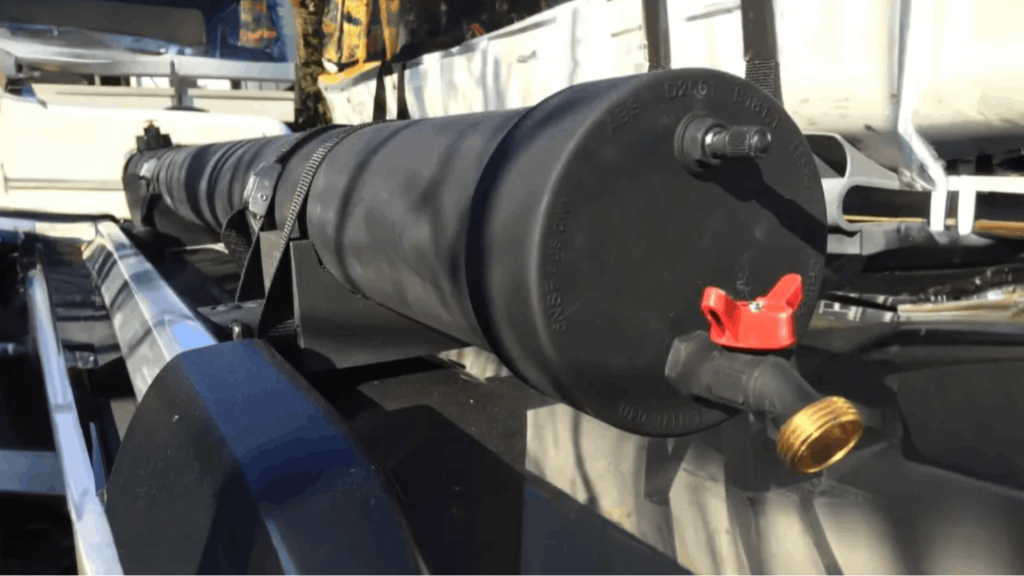
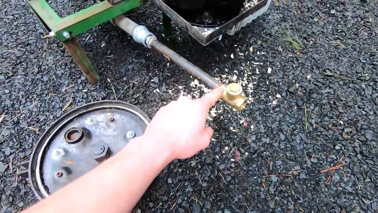
STEP 2 : ATTACHING AIR INTAKE AND SYN GAS OUTPUT PIPES
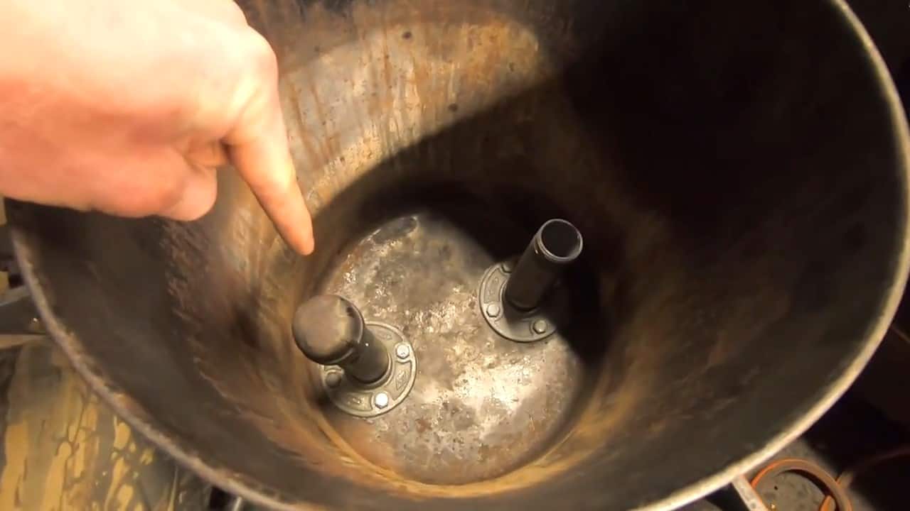
At the bottom of the pressure pot, two pipes are attached to facilitate the gasification process. One pipe serves as the air intake, while the other serves as the syngas suction output.
To attach the pipes, one and a quarter-inch pipe flanges are used to hold them tightly in place. This ensures that the pipes are securely attached to the pressure pot and can withstand the high temperatures generated during the gasification process.
The air intake pipe is responsible for bringing in air to the gasifier, which is necessary for the gasification process to occur. This pipe is positioned at the bottom of the pot, ensuring that air is supplied to the reactor at the right location.

The gasification process that produces syngas occurs within the reactor unit of the gasifier. The reactor unit is designed with specific features that facilitate the gasification process, including the air intake pipe, the syngas suction output pipe, and the passive shaker grate.
The air intake pipe is positioned at the bottom of the reactor unit, allowing air to enter the unit from below. This air supply is crucial for the gasification process, as it provides the necessary oxygen to support the breakdown of organic materials.
The middle section of the reactor unit is where the gasification process occurs. During this process, the organic materials within the reactor unit are heated, resulting in the production of syngas. The syngas suction output pipe is positioned in this section to collect the syngas produced during the process.
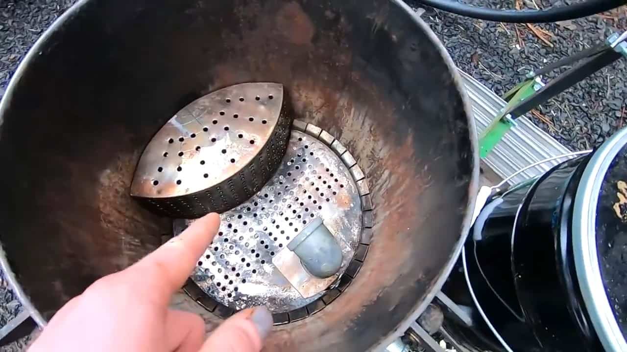
To ensure the efficiency of the gasification process, the ash that is produced during the process is sifted to the bottom of the reactor unit through a passive shaker grate. This ensures that the ash does not interfere with the production of syngas and that the gasification process can continue uninterrupted.
The output pipe is capped at the top to prevent residue ash from escaping, and small holes are drilled along the pipe to allow the syngas to pass through. This ensures that the syngas produced is clean and free of ash or other impurities.
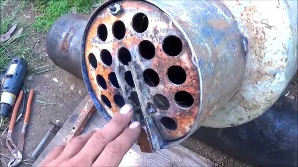
STEP 3 : MAKING A GRAGE INSERT
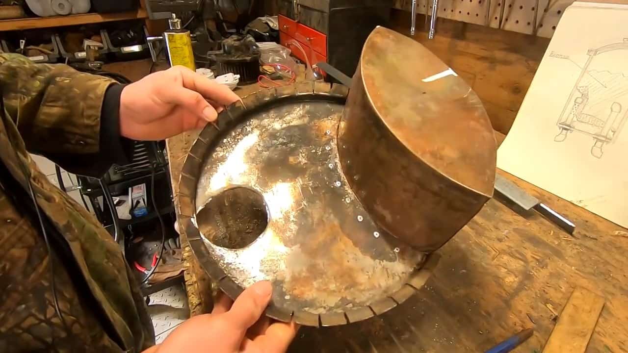
Once the pressure pot has been properly prepared and the necessary pipes have been attached, the next step is to build the grate insert. This is where the fuel will sit and burn during the gasification process.
The grate is made from the other stainless steel container that comes with the pressure spray painting pot. This container is cut to size and drilled with a quarter-inch drill bit to create a grid of holes along the surface.
The grate is positioned within the reactor unit so that it sits about two and a half inches off the bottom of the pot. This ensures that the fuel is positioned at the right height within the reactor unit to allow for efficient gasification.
The design of the grate is important to ensure that the fuel is able to burn effectively during the gasification process.
The grid of holes on the surface of the grate allows air to flow through, ensuring that the fuel is properly oxygenated. This allows for efficient gasification to occur and ensures the production of high-quality syngas.
To ensure that the grate is properly ventilated and able to facilitate efficient gasification, a grid of holes is drilled along its surface using a quarter-inch drill bit.
The holes are evenly spaced to allow for proper air flow throughout the grate.
Once the grid of holes has been drilled, the grate is carefully inserted into the reactor pot chamber. It is important to position the grate correctly within the chamber, so that it sits at the proper height within the pot.
The grate serves as a platform for the fuel to rest on during the gasification process. The fuel is placed on the grate and burned in a controlled environment to produce syngas.
The holes drilled into the grate allow air to flow through, ensuring that the fuel is properly oxygenated and able to burn efficiently.
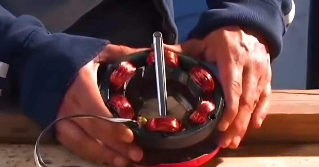
STEP 4 : REPLACING THE GASKET
To ensure that the gasifier operates effectively and safely, it is important to properly seal the lid of the reactor unit. The gasket on the back of the lid of the pot is first removed to make way for a new seal.
In its place, fiberglass rope is used to create a new gasket that can withstand high temperatures of up to 2000 degrees Fahrenheit.
The rope is wrapped around the lid to create a tight seal and ensure that gases produced during the gasification process do not escape.
The rope is secured in place using gasket cement and stove sealer to ensure a strong and durable bond. Once applied, the lid is carefully clamped in place to allow the gasket cement to dry and the seal to properly set.
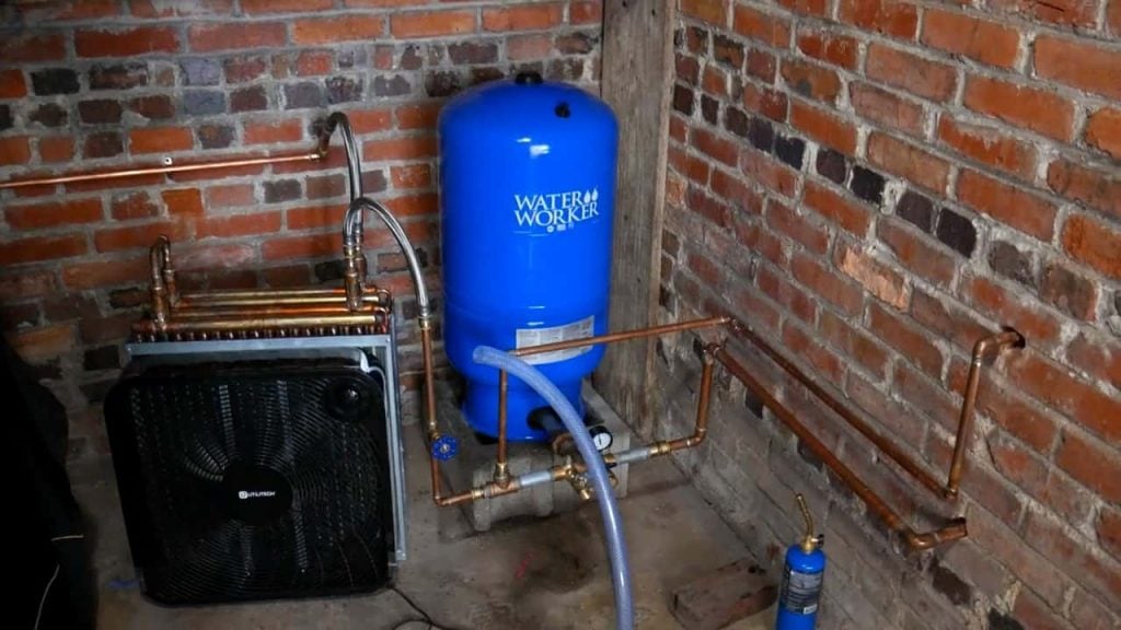
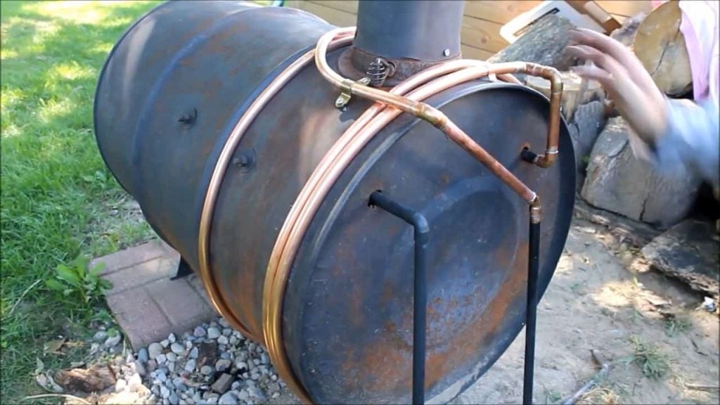
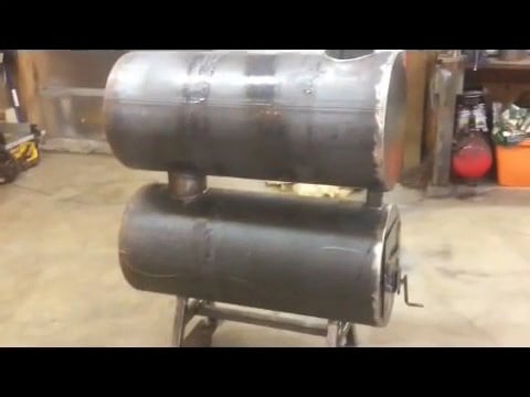
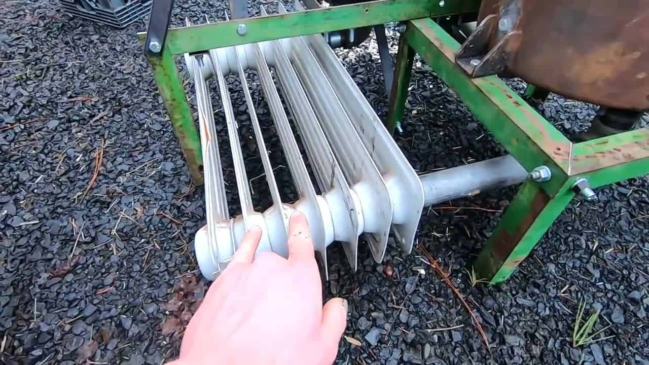
STEP 5 : BUILDING A CONDENSATE CATCHER
The gas produced during the gasification process contains tar and steam, which must be filtered out before the syngas can be used as a fuel source.
To accomplish this, a cooling and filtering system is built to condense the gases and remove any impurities.
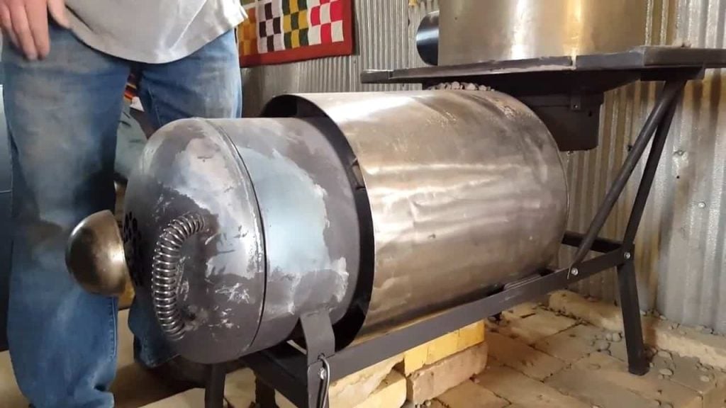
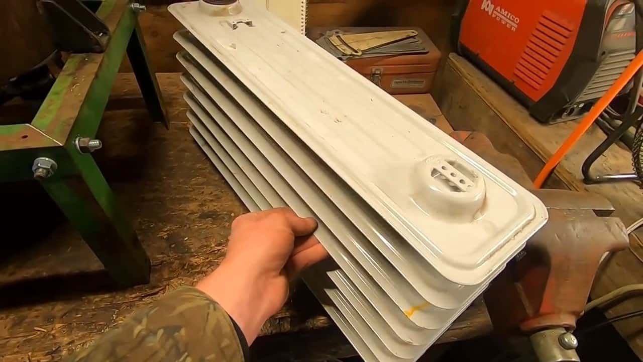
An old oil heater radiator is repurposed as a condensate catcher to help condense the gas and filter out any impurities.
The gas coming out of the reactor is connected to the radiator, which is designed to get most of the heat out of the gas, causing it to cool and condense.
By cooling the gas, the steam and tar present in the gas are able to condense back into their liquid form, allowing them to be easily removed.
STEP 6 : FILTERING SYSTEM
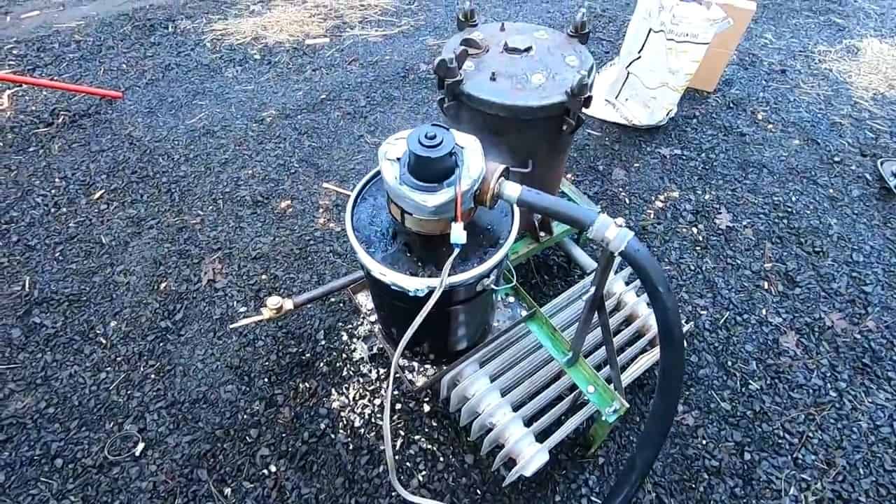
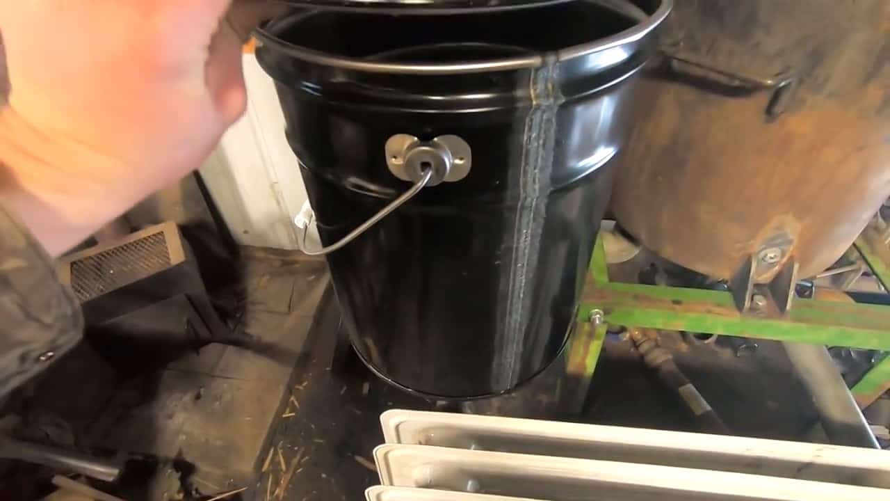
To further filter the syngas produced by the gasifier, a filtration system is built using a 5-gallon metal bucket. The output pipe from the radiator is attached to the bottom of the bucket using a flange.
The bucket is filled with a filter medium such as wood shavings or sawdust, which acts as a filter to trap any particulates and remove additional tar from the gas.
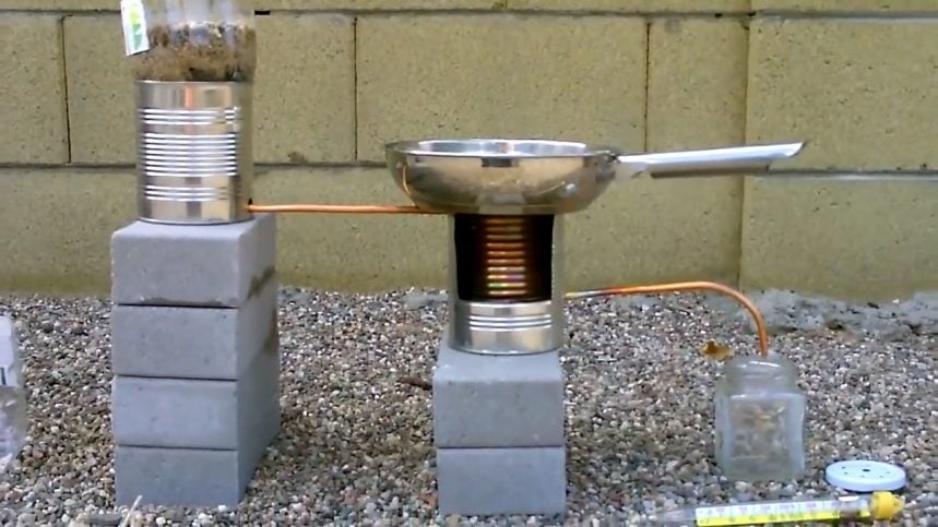
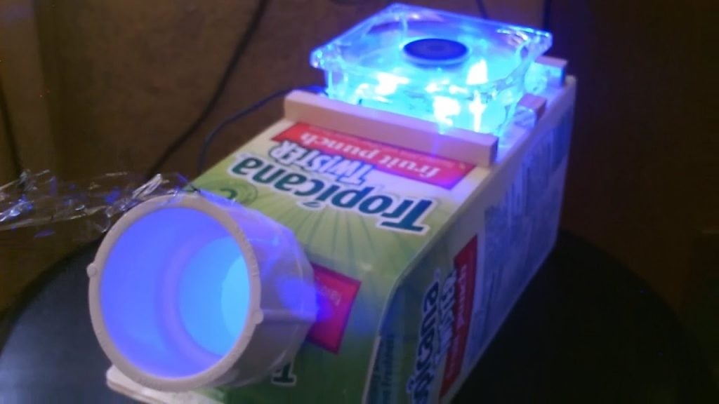
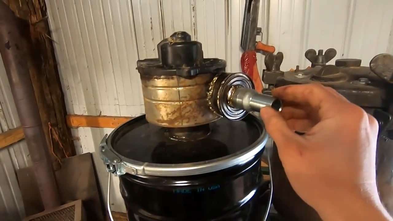
STEP 7 : ATTACHING A CAR AIR BLOWER
To help get the filtered syngas up to the point where it can be burned, an old car air blower from a Toyota is attached to the top of the bucket.
To support the blower motor, an old tin can is used, which is secured at the center of the top of the bucket. Another soup can is soldered to the side of the tin can, which acts as an attachment point for the output hose pipe.
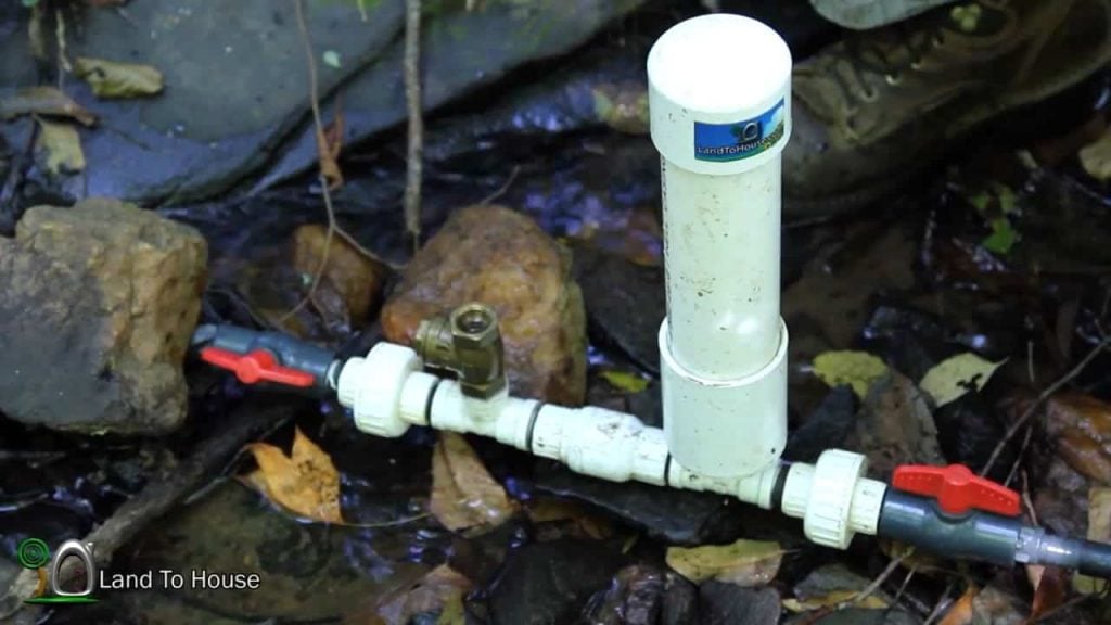
To ensure that there is not enough oxygen to cause the organic material in the reactor to combust and burn, a one-way gate valve is used.
This valve helps to regulate the flow of oxygen and prevents any backflow into the system, ensuring that the gasification process can occur without interruption.
The one-way valve is an essential safety component in the gasifier system, as it helps to prevent any flashbacks or dangerous situations that can occur when there is too much oxygen inside the reactor.
By limiting the amount of oxygen present in the system, the one-way valve ensures that the gasification process can occur safely and efficiently, without any risk to the operator or the equipment.
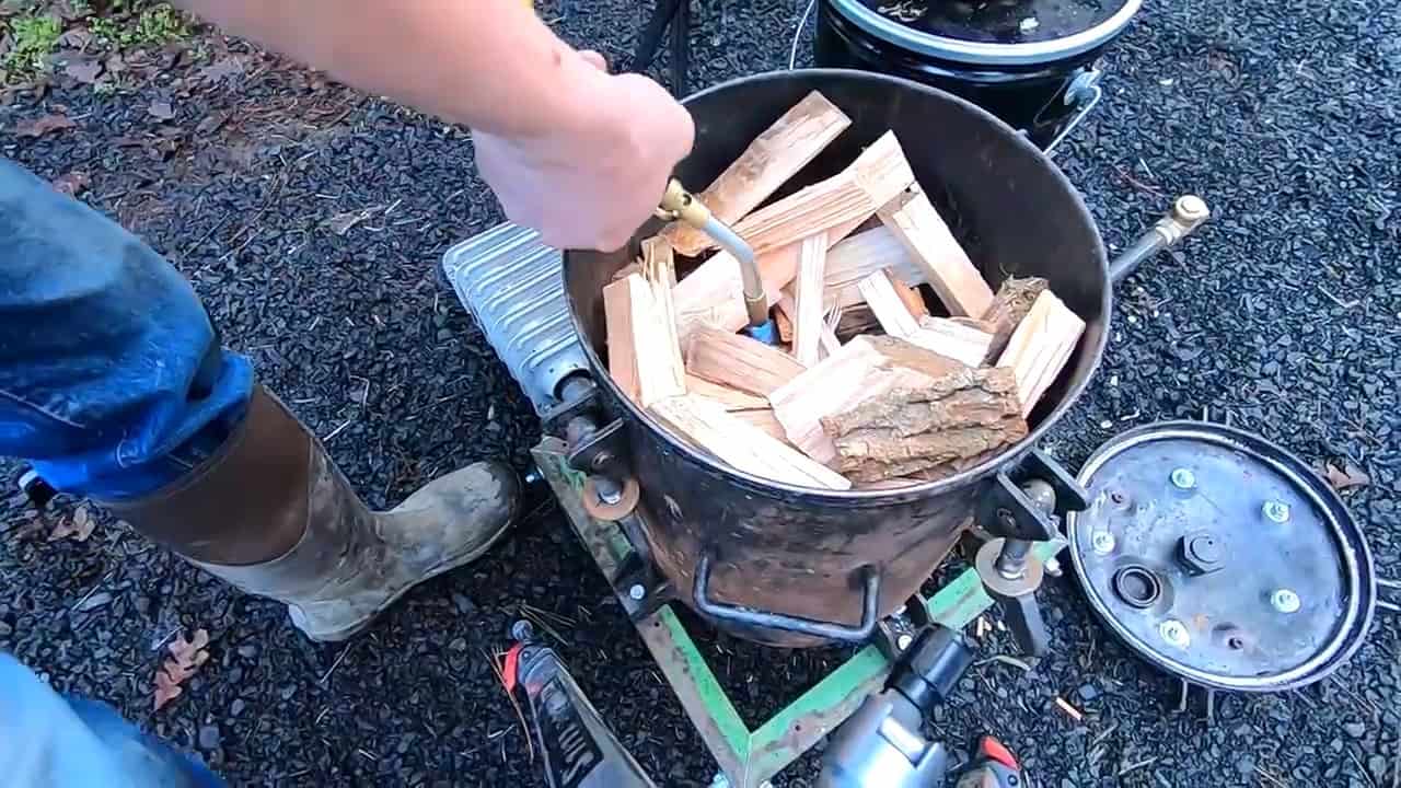
STEP 8 : LOADING THE REACTOR
The final step in building the off-grid wood gasifier is to load the reactor with wood sticks and a starter material to begin the gasification process.
The starter material consists of cloth, paper, and wood pellets, which are sprinkled on top of the wood sticks to create a small, initial fuel source.
When loading the reactor, it’s important to pack the wood sticks tightly, leaving a small space in the center to allow for air flow. Once the reactor is loaded, the fans are turned on to increase the airflow and promote combustion.
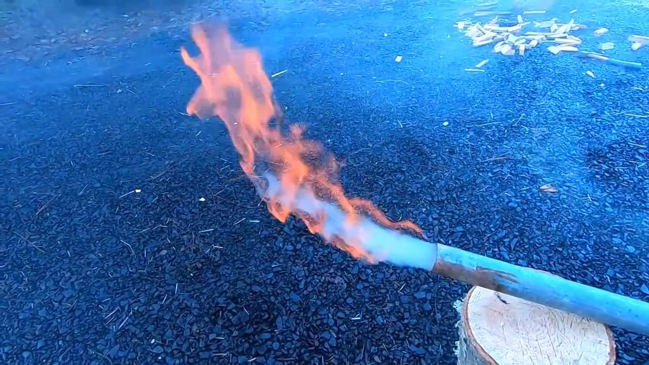
Next, the ignition process is initiated. This involves lighting the starter material using a lighter or match, and allowing it to burn and ignite the wood sticks.
Once the wood sticks have caught fire and the gasification process has begun, the fans continue to blow air into the reactor, ensuring a consistent supply of oxygen to sustain the combustion process.
Image Credits : Randomn