Solar heat collectors are a good supplemental heating source that can provide homeowners with heat for their homes when the sun is shining.
Solar collectors are box-like structures that capture the energy from the sun and convert it into usable energy for heating purposes. Inside the collector, solar energy is simply converted into usable thermal energy.
On the front side of the solar collectors, a clear panel or glazing material typically polycarbonate sheeting is used. Single pane glass, and double pane glass face towards the sun and allow the sunlight into the collector box.
On the inside of the collector, box is a heat exchanger or an absorber. The heat exchanger or absorber is responsible for transferring the heat of the sun into a usable thermal heat source.
The heat exchanger is suspended or attached inside the collector box and should be coated flat black with a high heat temperature resistant paint.
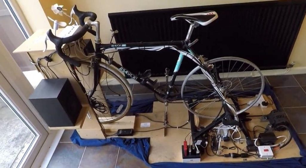
This project goes over the build of an entirely self-contained Solar Air Heater using no grid power whatsoever. The unit draws the cold air from the room and exhausts hot air into the room using 2 5V DC brushless 7 vane case fans.
These fans are powered by a 16 Watt Amorphous solar panel. Both the intake and exhaust pipes are of 5-inch diameter.
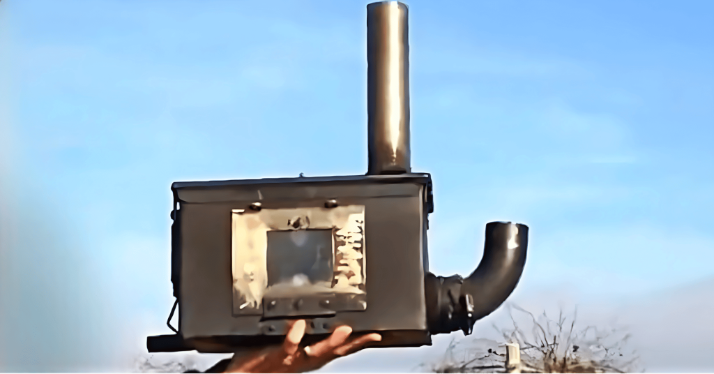
STEP 1 : MAKING THE COLLECTOR BOX
To construct a solar air heater, a box must first be fabricated to house the various components of the heating system.
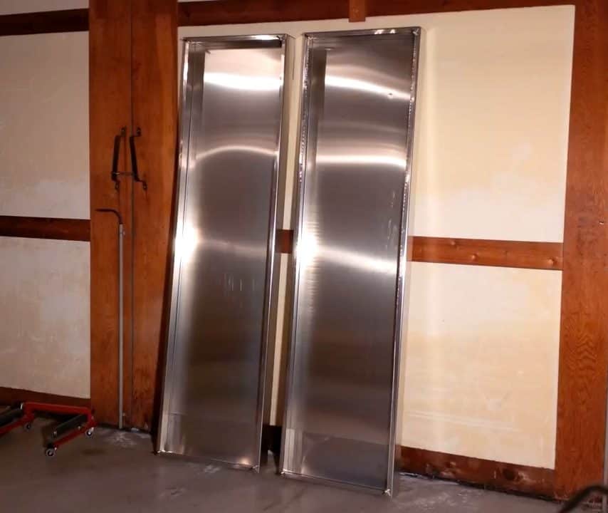
For this purpose, 5052 aluminum alloy sheets are used, which offer excellent corrosion resistance and high strength-to-weight ratio.
The dimensions of the box are 91 inches tall and 24 inches wide, providing ample space for the components to be installed. A one-inch flange is incorporated into the design, which is bent using a metal bending brake to create the sides of the box.
The flange adds structural integrity to the box, ensuring it can withstand the elements and operate efficiently.
To complete the box, top and bottom caps are bent to fit on the respective ends of the box. The distance between the bends of the bottom caps is decreased by one millimeter to allow the caps to fit inside the solar airbox, which facilitates drainage.
This helps to prevent the buildup of moisture inside the box, which can lead to corrosion and reduce the system’s efficiency.
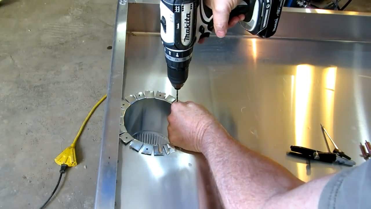
Once the aluminum box for the solar air heater is constructed, the next step is to secure the top and bottom caps. To accomplish this, a smaller diameter drill bit is used as a pilot before drilling to the final size for the rivet.
This ensures that the holes are precisely aligned and prevents any damage to the material.
To hold the two pieces together during the assembly process, Cleco fasteners are used. These fasteners are temporary and are used to maintain the exact position of the material before the permanent rivets are installed.
Clecos provide an efficient and accurate way of aligning materials without the need for additional clamps or fasteners. They can be easily removed once the permanent rivets are in place, leaving behind a clean and secure joint.

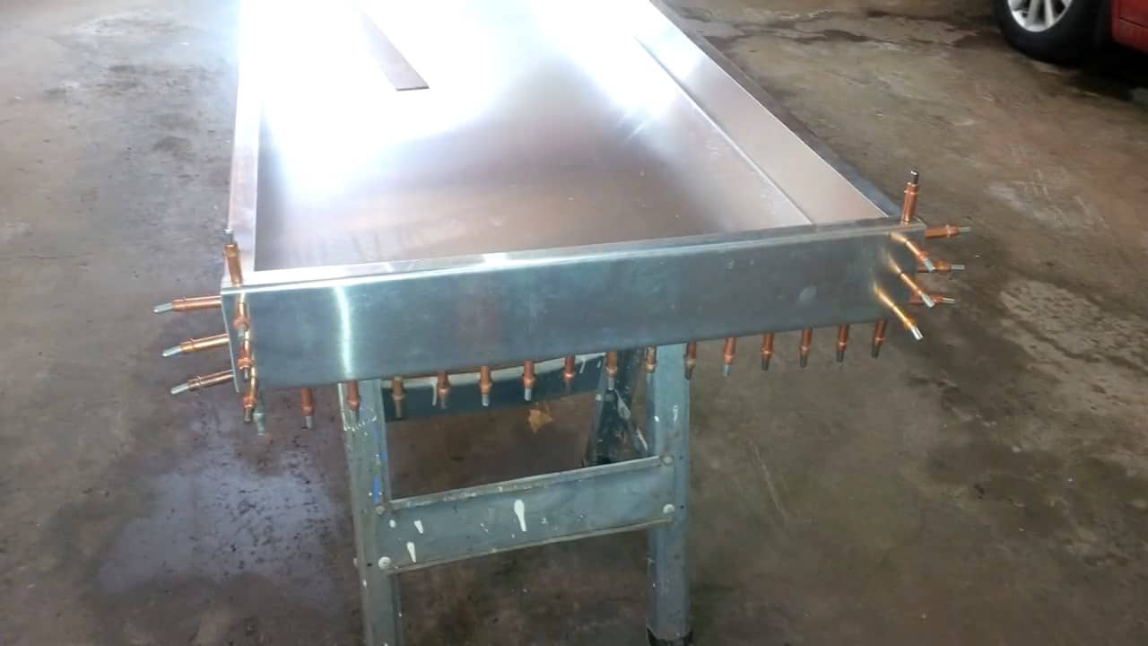
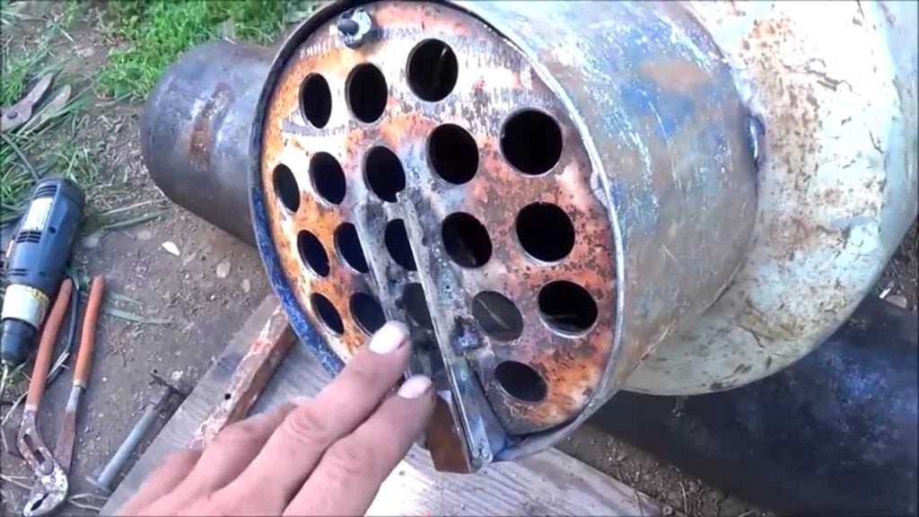
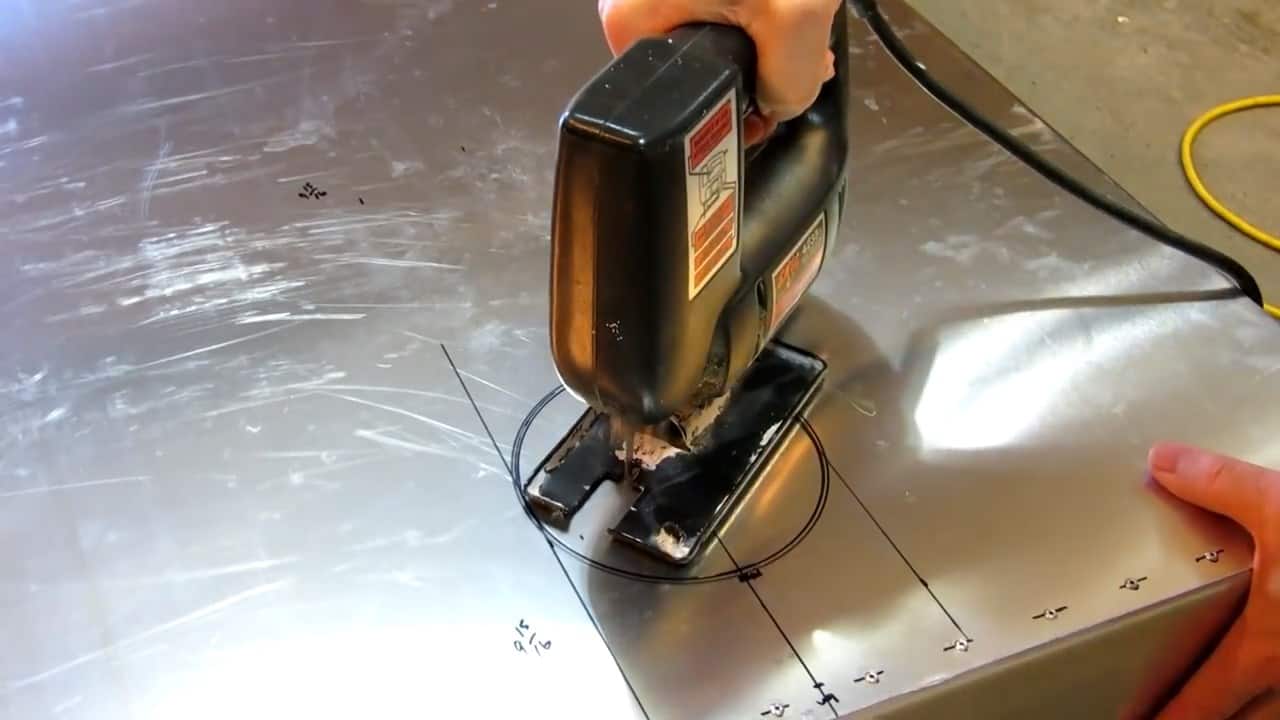
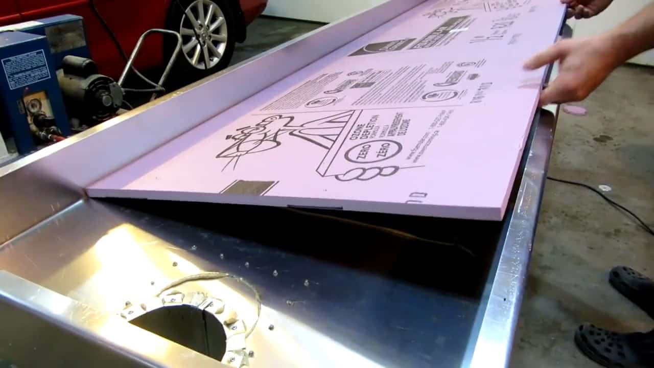
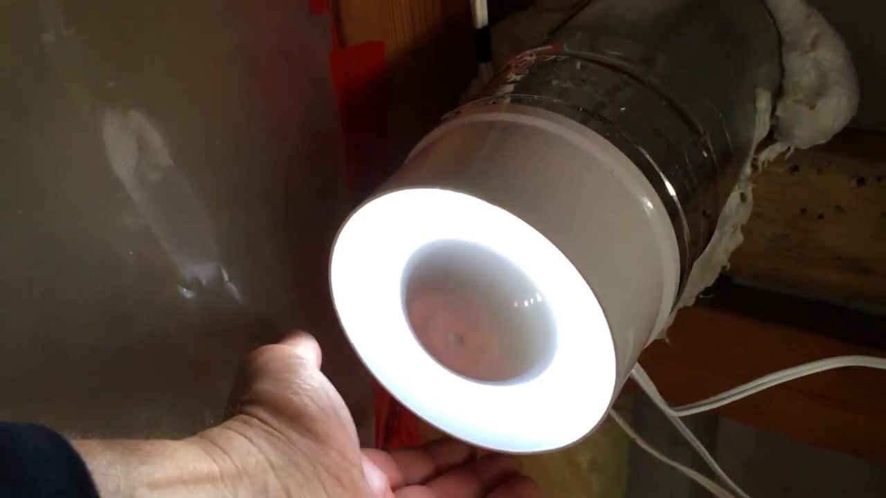
To install the plenums in the solar air heater box, two five-inch holes are cut at both the top and bottom of the box.
These holes are carefully measured and placed to ensure that the plenums fit securely and properly align with the airflow channels.
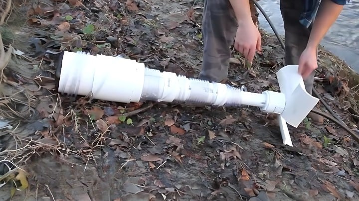
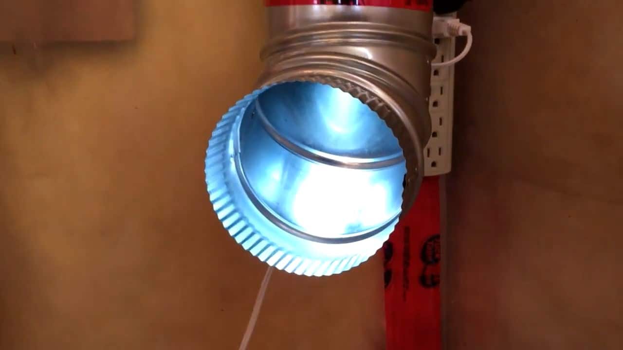
The intake and exhaust pipes for the solar air heaters are manufactured from a single piece of five-inch HVAC plenum, which is a type of ductwork used in heating, ventilation, and air conditioning systems.
This ductwork is durable, easy to work with, and provides a smooth surface for optimal airflow.
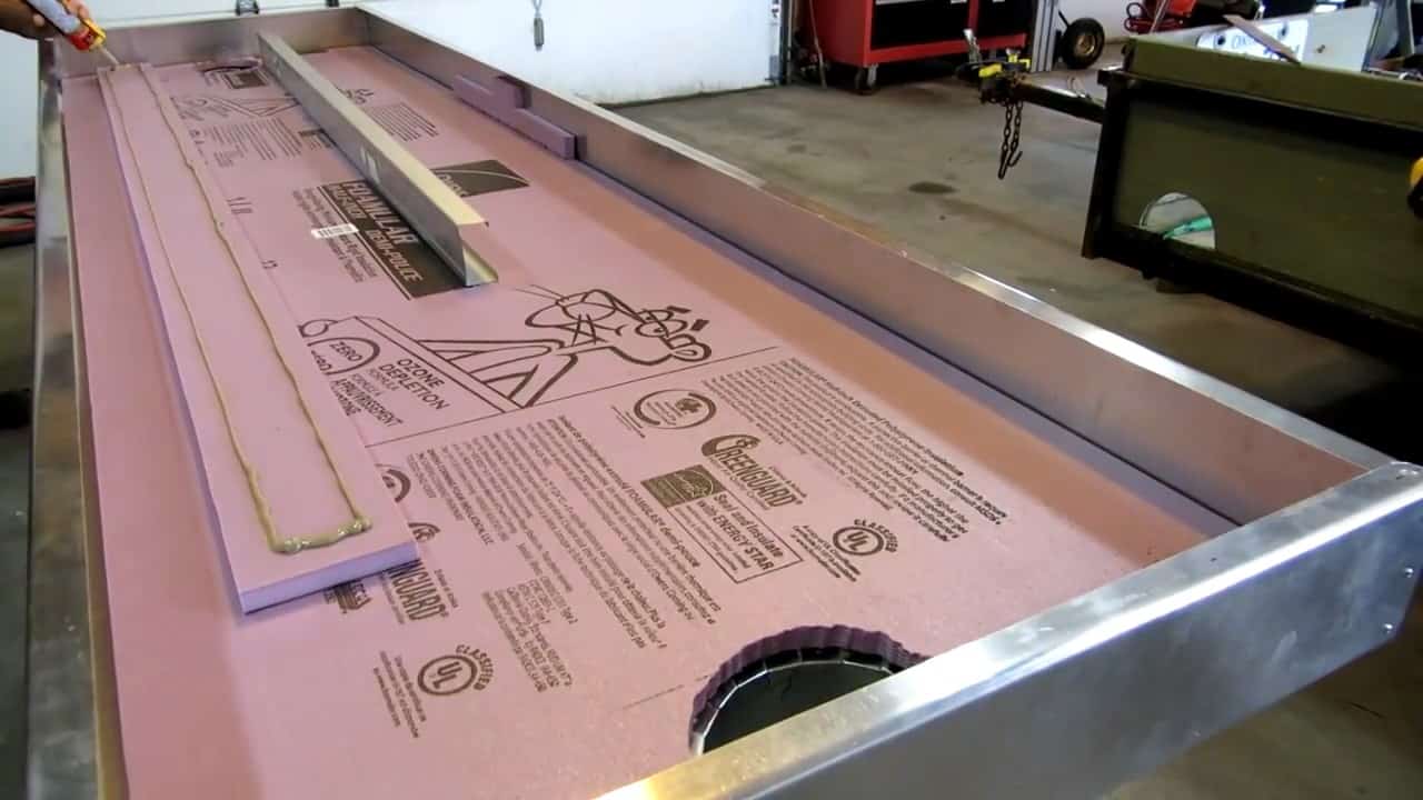
Once the plenums are inserted into the holes, they are secured using construction adhesive. This adhesive is chosen for its strong bonding properties and ability to withstand high temperatures.
The adhesive ensures that the plenums are firmly held in place and air can flow efficiently through the solar air heater.
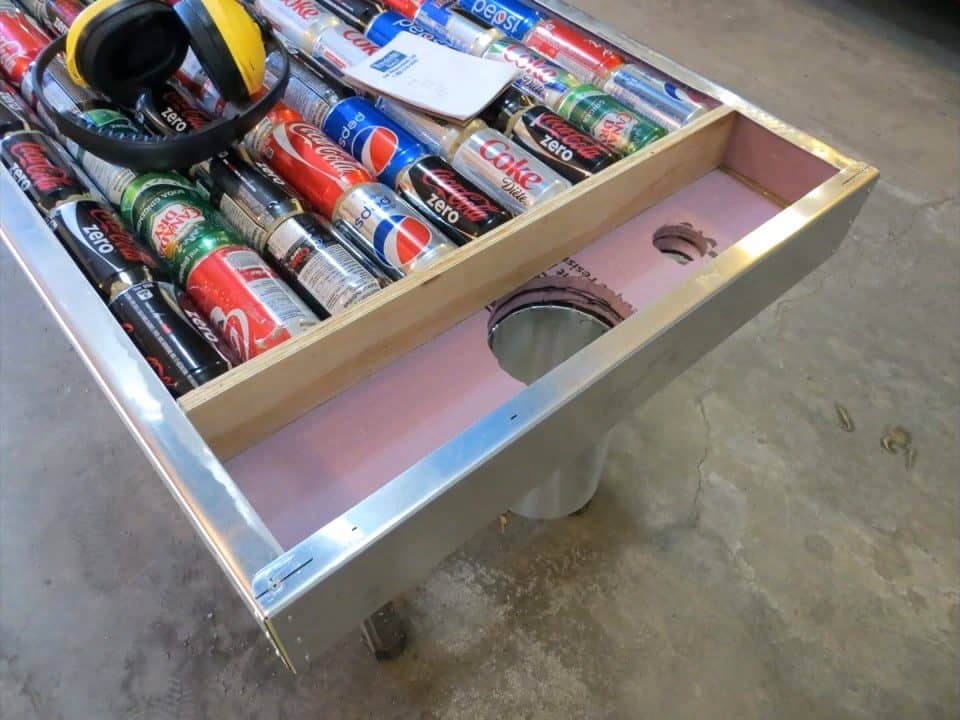
To prevent heat loss and increase the efficiency of the solar air heater, the back of the box is insulated using two sheets of half-inch foam. In addition to the back, one sheet of half-inch foam is also installed on the sides of the box.
A pneumatic air file is used to cut the foam sheets to size and shape, ensuring a snug fit and maximum insulation. The foam helps to trap the heat inside the box and prevent it from escaping through the walls, ensuring that the warm air is directed towards the intended space.
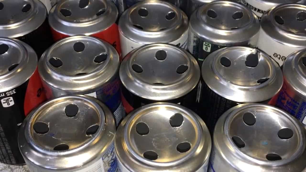
Next it’s time to install a snap action thermostat in the exhaust manifold. This will help you monitor the temperature of the air that will be coming into your house.
It’s important to make sure that the intake and exhaust manifolds are properly sealed so that all of the air goes through the interior of the cans.
This means that the manifold itself needs to be sealed tightly against the interior of the heat box.
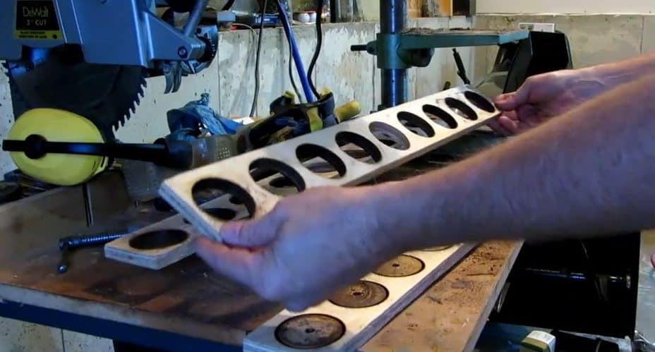
To create the intake and exhaust manifolds for your solar air heater, you will need two sheets of half-inch plywood. Using a jigsaw or circular saw, cut nine holes in each sheet to make space for the cans.
Make sure that the holes are evenly spaced and sized to match the diameter of the cans.
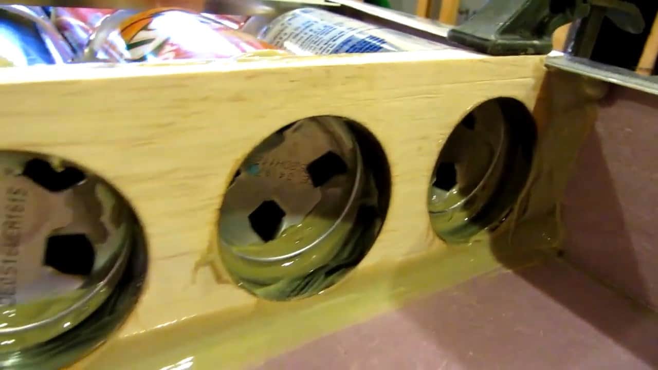
Once the holes are cut, secure the manifolds in place against the cans using PL construction adhesives. Be sure to apply enough adhesive to create a strong, durable bond between the manifolds and the cans.
It’s also important to make sure that the manifolds are properly aligned with the cans to ensure optimal airflow.
STEP 2 : COATING THE COLLECTOR BOX
The flat black paint used inside the collector box plays a critical role in the efficiency of the solar heat collector. Its primary function is to absorb the maximum amount of heat energy from the sun.
It is essential to choose a flat finish black paint, as opposed to a reflective coating. Reflective paint will reflect the sun back outside of the collector, resulting in a significant loss of potential energy.
The flat black paint, on the other hand, assists with trapping the heat energy and preventing it from being reflected away from the collector.
Once the sun’s energy enters the collector box through the glazing, the absorber’s material and flat black paint work together to efficiently absorb the heat and begin to warm the air inside the collector.
As the air warms up inside the collector and around the absorber, it will naturally expand and rise, creating a convection current. This process of warm air rising will continue as long as the sun is shining, leading to a constant circulation of heated air.
The warm air’s circulation is aided by the friction generated between the absorber and the air passing over and through it. This process creates an opportunity for the air to absorb more heat from the absorber surface and get heated by the sun.
STEP 3 : INSTALLING VENTS
After the air is heated by the absorber inside the collector, it needs a way to circulate through the box and into the intended living space.
To achieve this, we install two vents on the backside of the solar collector facing towards the room or space that requires heating.
The vent at the top of the collector allows the heated air to flow into the room, while the vent at the bottom allows cooler air to return to the collector for re-heating.
Installing both a return vent at the bottom and a supply vent at the top of the solar collector allows for the natural convection process to occur.
As the air inside the collector absorbs heat from the absorber, it begins to warm and expand, causing it to rise up and out of the collector.
This natural upward movement of the warm air creates a convection current, which draws cooler air from the room or conditioned space into the bottom of the collector box.
The return vent at the bottom of the collector allows for the cooler air to enter and circulate through the system, while the supply vent at the top allows for the heated air to be distributed into the room or conditioned space.
The solar collector functions by creating a convection current within the room. The cooler, denser air at the bottom of the room is pulled through the collector, where it is heated by the absorber and transformed into warm air.
The warm air then exits the collector through the supply duct and is circulated back into the room, effectively raising the ambient temperature.
By removing cooler air from the bottom of the room and replacing it with warm air, the collector helps to maintain a comfortable living environment.
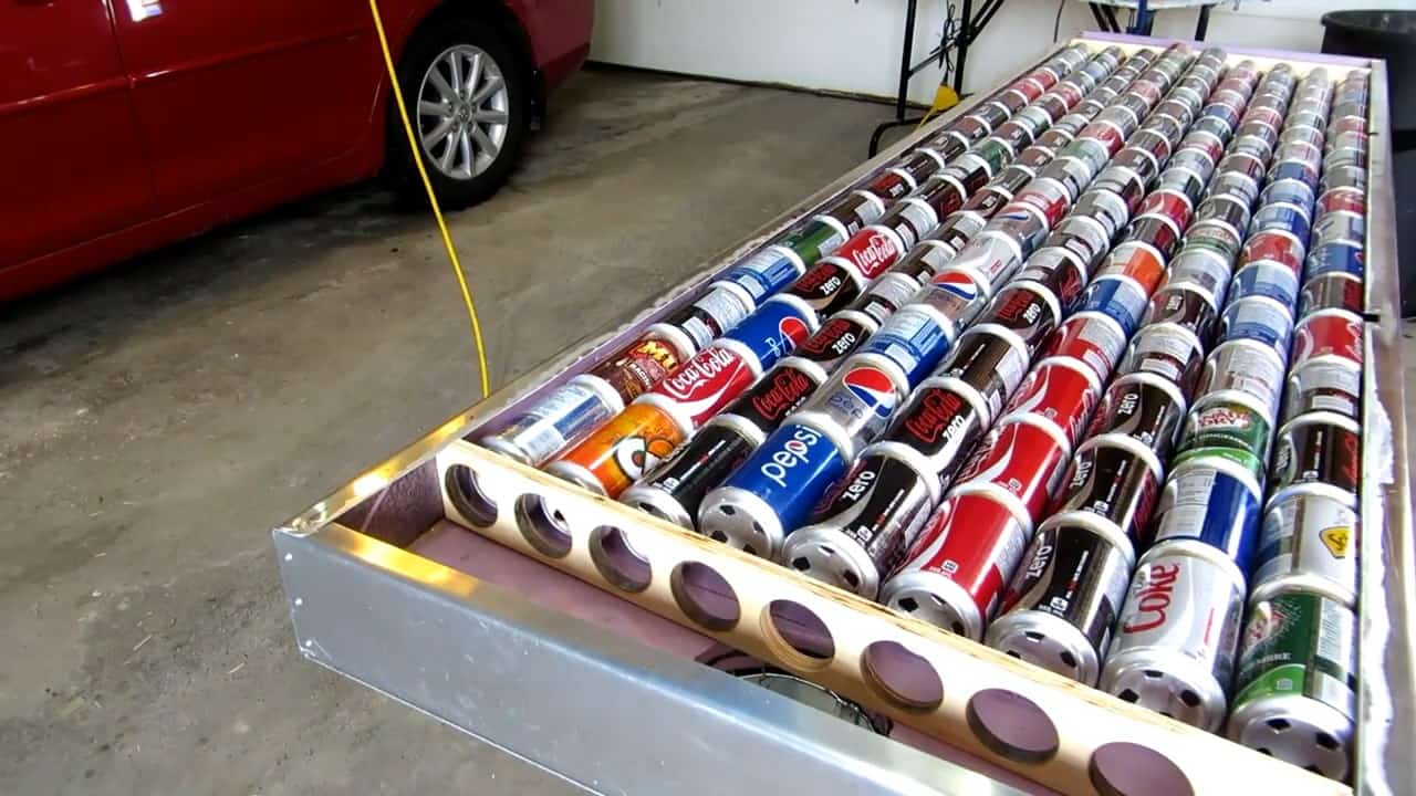
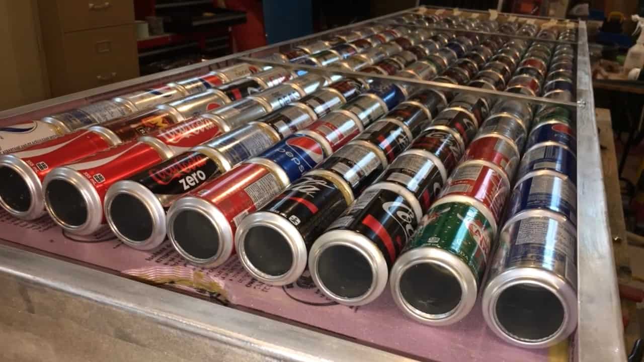
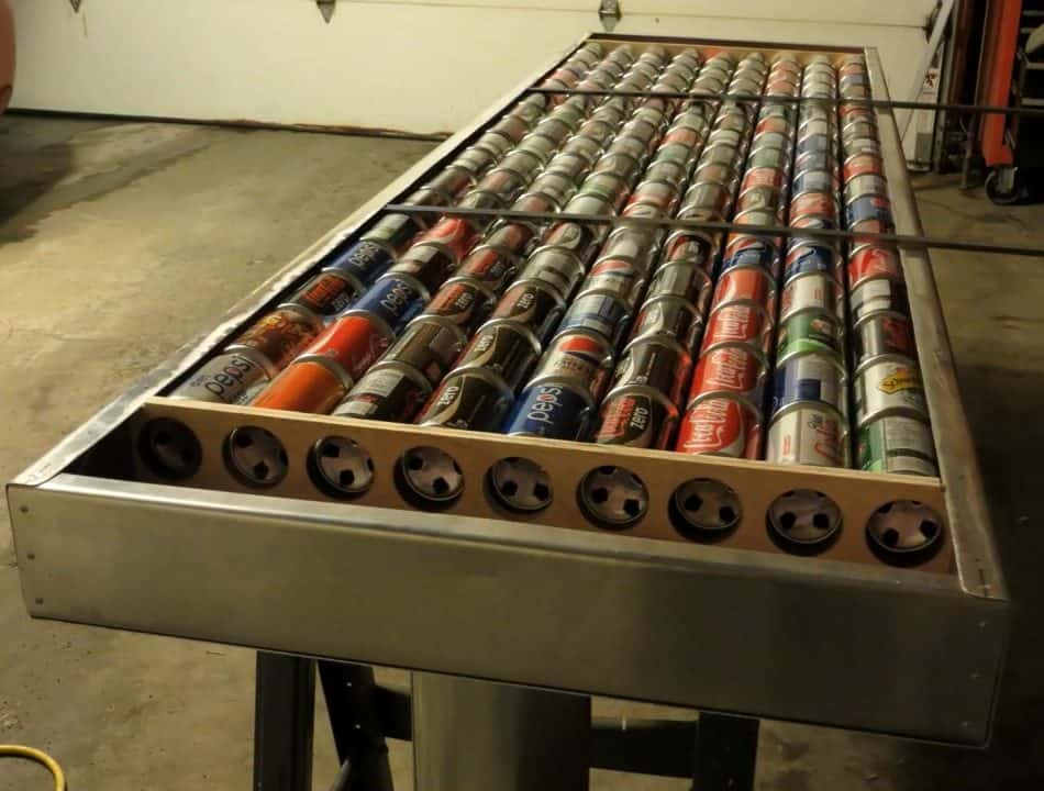
The solar collector is constructed using 153 355ml soda cans arranged in 9 rows of 17 cans each. To maximize the absorption of sunlight, each can is coated with flat black paint.
This coating prevents any reflection of sunlight and ensures that all energy from the sun is absorbed. Additionally, the collector is equipped with a five-inch intake and exhaust manifold at the bottom and top of the unit.
The manifold design ensures that all air is directed through the interior of the aluminum cans, maximizing the exposure of air to the heat absorbed by the cans.
STEP 4 : BUILDING THE HEAT EXCHANGER
To maximize the heat transfer from the sun to air within a given space, we need to build a better heat exchanger. Solar air heating systems use air as the working fluid for absorbing and transferring solar energy.
Transferring heat from one place to another by definition is a heat exchanger.
When the sun heats the metal, the hot metal heats the air circulating over the metal of the heat exchanger. The job is to capture radiation from the sun and transfer this thermal energy to air via conduction heat transfer.
Heat transfer output depends on the rise in temperature and the airflow.
In order to minimize heat loss through the plexiglass, it is imperative to keep the absorber temperature as low as possible.
This is because the higher the absorber temperature, the greater the amount of heat lost through the glass.
One way to achieve this objective is by increasing the airflow while maintaining the same amount of solar energy extraction.
The increased airflow helps to transfer the absorbed heat away from the absorber quickly, thus preventing the absorber temperature from rising too high.
By doing so, we can ensure optimal performance of the solar collector while minimizing heat loss through the plexiglass.
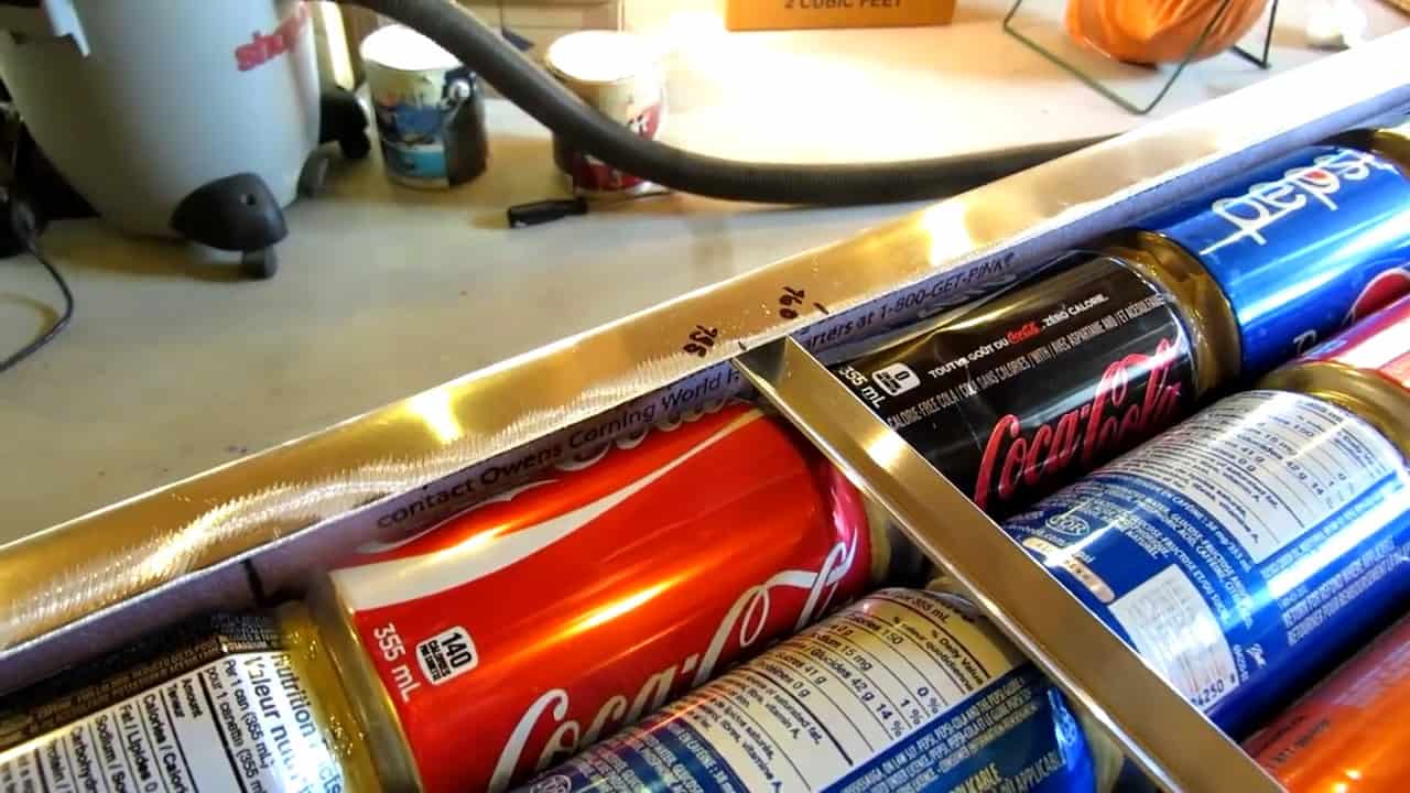
STEP 5 : INSTALLING THE AIR TUBES

To ensure that the solar air tubes remain securely in place within the collector box, we utilize two 1/16th half-inch 6063 aluminum extrudes.
These extrudes apply just the right amount of pressure to the cans, firmly holding them against the back of the heating chamber.
This prevents any movement or displacement of the cans, which can cause a reduction in the efficiency of the solar collector.
The aluminum extrudes are carefully installed in a manner that guarantees the tight fit of the cans and that they do not become loose over time.
The use of these extrudes is critical in ensuring optimal performance of the solar air heating system.
To ensure maximum absorption of solar radiation, it is essential to coat the solar air heater box with a high heat black rest-oleum paint. This paint is designed to withstand high temperatures and is ideal for solar energy applications.
To achieve optimal results, three separate coats of the paint are applied to the box, with each coat being applied within 60 minutes of the previous one.
STEP 6 : IMPROVING CONDUCTION
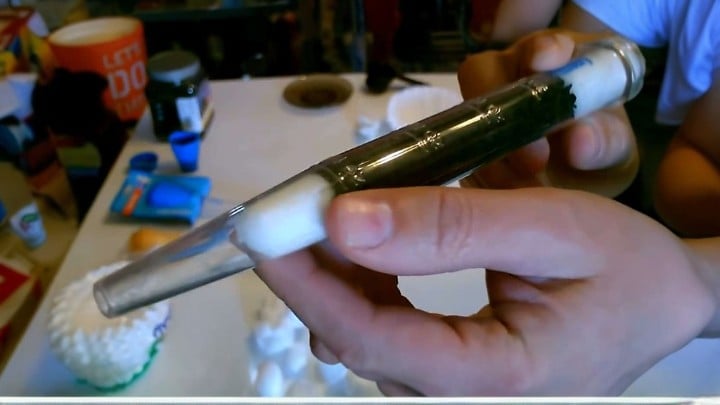
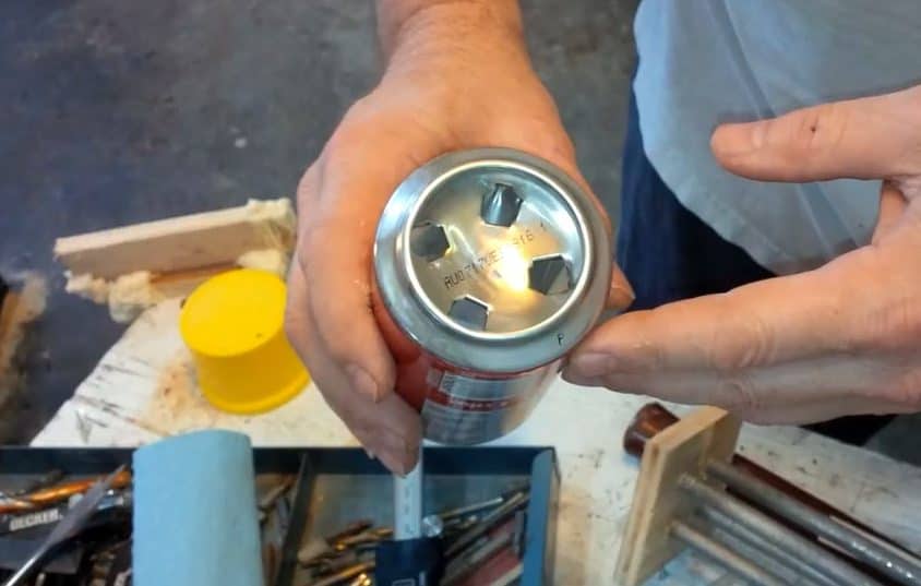
To enhance the conduction heat transfer without hindering the airflow significantly, we utilize a technique that disrupts the airflow within the solar air tubes.
This involves creating a baffle within some of the soda cans to increase turbulence.
To distribute the airflow evenly, these baffle cans are placed at regular intervals across the tubes.
We strategically place the first baffle cans on the second row from the bottom to disrupt the airflow early on.
The second baffle is then located in the 10th can to further enhance the turbulence.
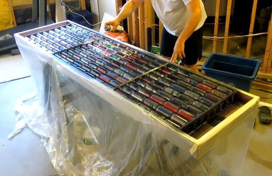
To facilitate the stacking of the empty soda cans, we construct a practical assembly tray in the shape of a “V” using a leftover baseboard. This support structure ensures that the cans remain stable and vertical during the assembly process.
We use PL Premium construction adhesive, a high-quality adhesive that is water-resistant, paintable, and nonshrinking, to securely bond the cans together. To ensure that the adhesive is evenly distributed, we carefully rotate the cans as we apply the adhesive.
The “V” channel created from the baseboards provides a precise guide for the cans, helping to maintain their position and prevent them from shifting during the assembly process.
STEP 7 : INSTALLING THE PLEXIGLASS
To ensure a secure and durable seal between the Plexiglas and the solar air heater, clear silicone adhesive is the primary method of adhesion. After carefully positioning the Plexiglas on top of the heating chamber, a 1/8 inch pilot drill is used to create a hole through the Plexiglas.
Then, a full tube of silicone is applied around the perimeter of the Plexiglas before laying it down.
To optimize the performance of the solar air heating system, we have incorporated two 16 Watt Sailflo Duct Exhaust fans, each with the ability to move up to 141 CFM (Cubic Feet per Minute) of air.
These high-quality fans are powered by a small solar panel, making them an efficient and sustainable choice.
One of the fans is positioned to blow air into the chamber, while the other is placed to suck air out. This strategic placement helps to overcome any additional internal airflow resistance that may have been built into the design, ensuring that the system operates at its maximum potential.
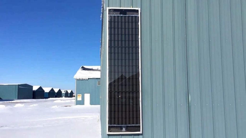
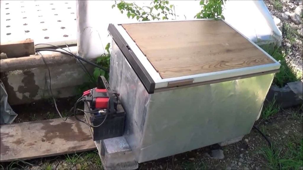
STEP 8 : INSTALLING THE COMPLETED SOLAR AIR COLLECTOR
Once the solar air collector is completed, it is installed outside in a south-facing direction to capture the maximum amount of sunlight.
After installation, we measure the temperature difference between the incoming and outgoing air while moving 141 cubic feet of air per minute with the help of the installed Sailflo Duct Exhaust fans.
To calculate the amount of heat transfer, we multiply the CFM and temperature rise by a factor of 1.08, which is a commonly used formula for solar air collectors.
This calculation helps to determine the efficiency of the solar air collector and ensures that it is performing optimally.
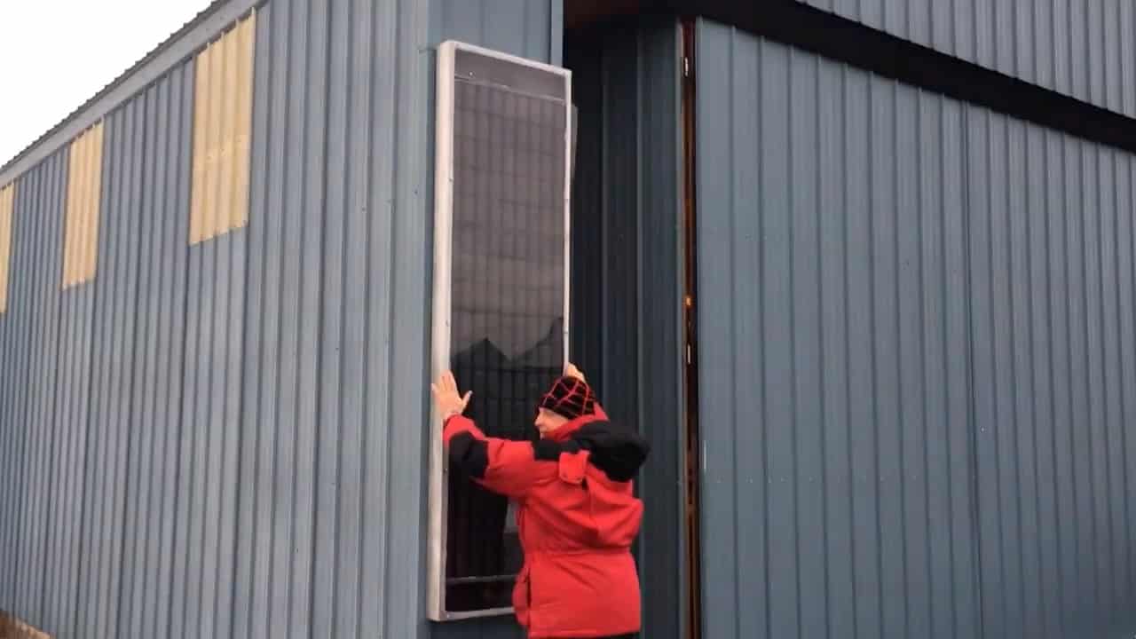
Image Credits : Dwayne Price