In this article, we delve into the detailed construction process of a homemade waste oil garage heater, which utilizes an old 55-gallon drum and a propane tank.
This multi-purpose setup serves the dual function of providing heat to a garage or workshop while also doubling as a cooker.
STEP 1 : BUILDING A WASTE OIL BURNER
The first and most important step in building this waste oil garage heater involves creating the Waste Oil Burner Unit.
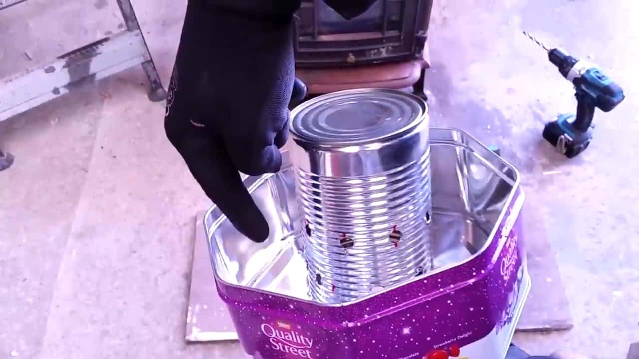
This is achieved by utilizing a four-inch tin can and a candy tin, both of which are readily available at local hardware stores.
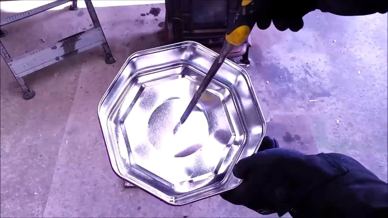
Begin by placing the tin can in the center of the candy tin and marking around them. Cut out a hole using a chisel, ensuring that it is the correct size to accommodate the tin can.
It is essential to take great care in cutting the hole to ensure that it is the correct size and placed centrally. This will prevent any issues during the heating process.
Once the hole is cut, drill around 15 small holes around the tin can, using a drill bit that is slightly smaller than the size of the tin can.
These holes will serve as the air inlets for the burner, providing a fresh supply of oxygen for combustion. The tin can itself functions as a chimney, which directs the airflow to the combustion area.
Insert the tin can into the hole at the center of the candy tin, ensuring that it fits snugly. The open end of the tin can should be placed facing down towards the hole to allow for proper airflow.
This design ensures that the burner uses just over two liters of used waste oil per hour, while still generating an impressive amount of heat.
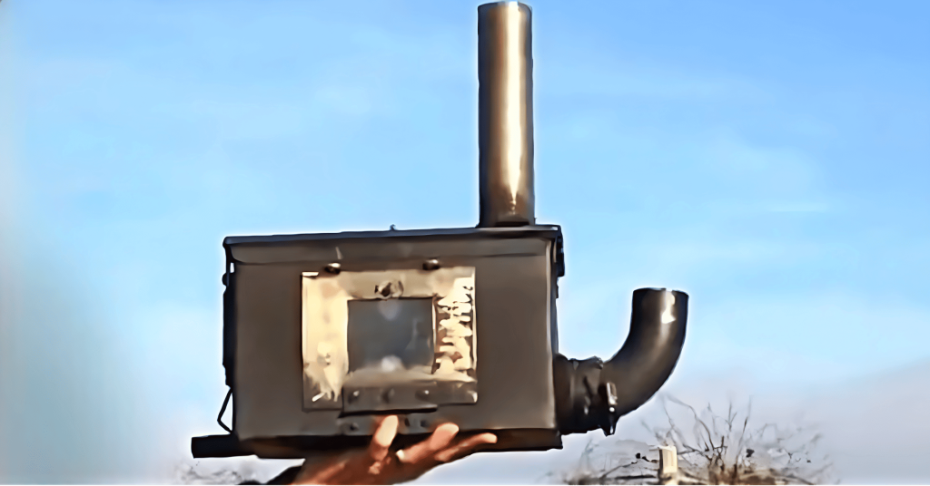
STEP 2 : WORKING WITH THE PROPANE TANK
Before beginning work on the propane tank, it is essential to ensure that it is empty and free of any residual propane gas.
This can be done by carefully opening the valve and allowing the gas to escape in a safe and controlled manner.
Once the tank is confirmed to be empty, the next step is to fill it with water and allow it to sit for at least a day. This step is crucial as it helps to remove any remaining propane gas that may be trapped within the tank, ensuring that it is safe to work with.
After the tank has been allowed to sit for an appropriate amount of time, it is ready to be disassembled. Begin by cutting the tank into two sections, using a saw or other appropriate cutting tool.
The tank sections are then divided into two separate chambers, with the top chamber measuring seven inches in height, and the bottom chamber measuring three inches.
These chambers will serve as the upper and lower sections of the propane tank, respectively.
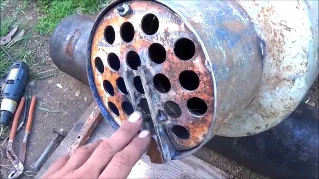
To ensure proper ventilation and exhaust, two openings are cut into the top of the tank. These openings will allow for the fumes from the burning waste oil to escape, while also providing a constant supply of fresh air for combustion.
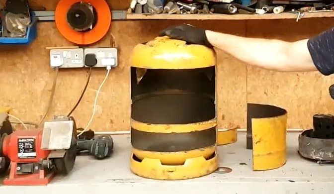
STEP 3: LOWER AND UPPER CHAMBER
In this step, we focus on the installation of a disc separator and the creation of doors for the upper and lower chambers of the propane tank.
Firstly, we create the disc separator by cutting a 4mm steel plate into a circular shape with a hole in the middle. This disc will be placed in between the upper and lower chambers of the propane tank.
The purpose of this separator is to ensure that the air intake and exhaust are appropriately managed and that the burner unit operates efficiently.
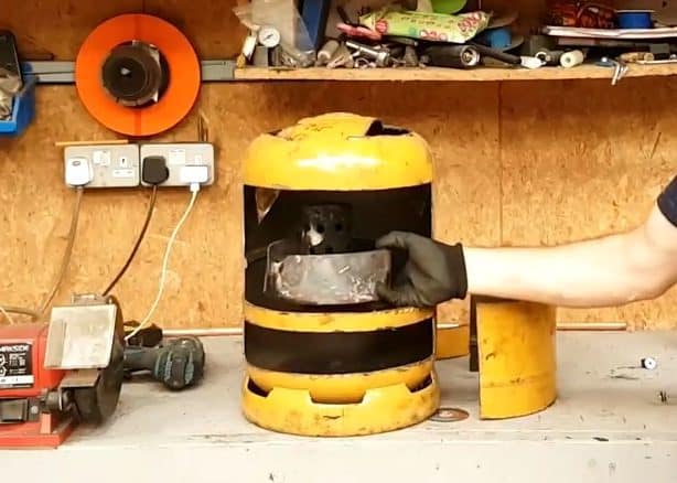
The tin can burner unit is then placed inside the upper chamber of the propane tank. This placement ensures that the combustion occurs in the upper chamber, while the lower chamber serves as the air intake.
By separating the combustion and air intake chambers, the system becomes more efficient, reducing the risk of incomplete combustion and enhancing safety.
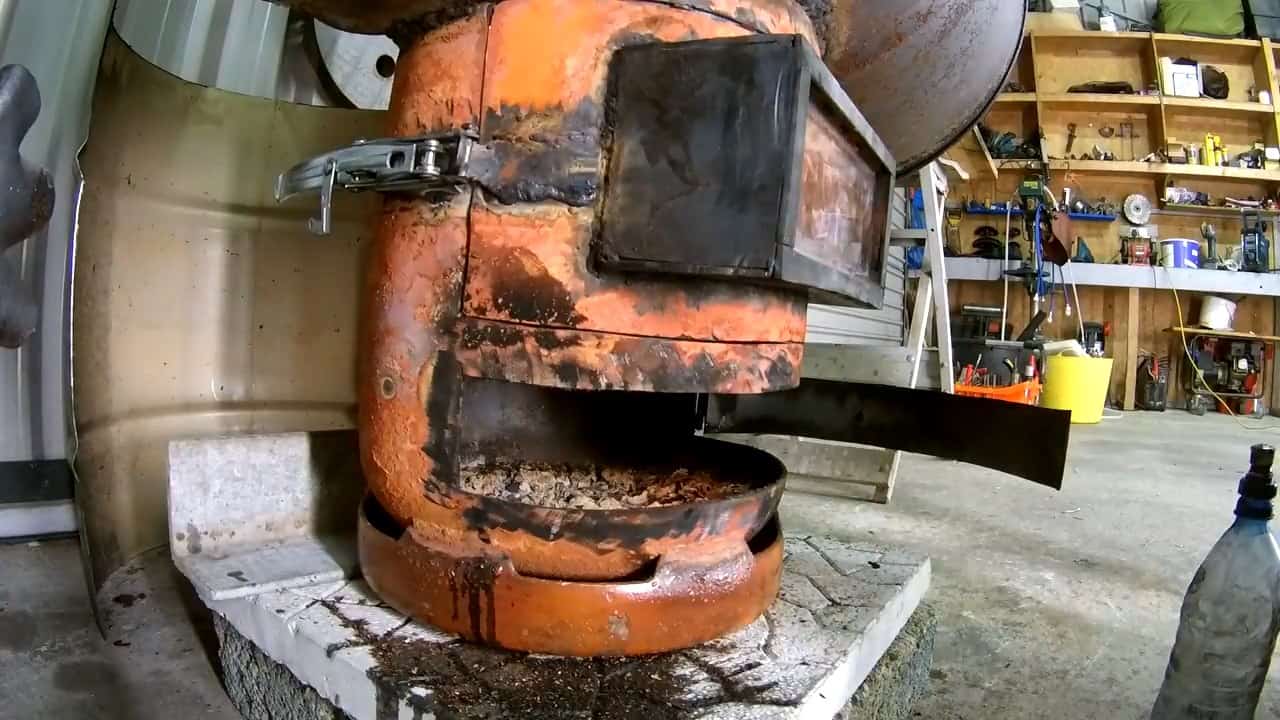
Next, we create doors for both chambers, using the leftover cut pieces of the propane tank. The door for the upper chamber is welded with a screen for viewing purposes, allowing for monitoring of the combustion process.
The doors also serve as an additional safety measure, ensuring that the contents of the tank remain contained.
The air for the combustion process is drawn from the lower chamber, passing through the disc separator hole, and entering the burner unit.
This carefully controlled airflow helps to ensure that the system operates efficiently and safely.
STEP 4 : HEAT RADIATOR AND A COOKTOP
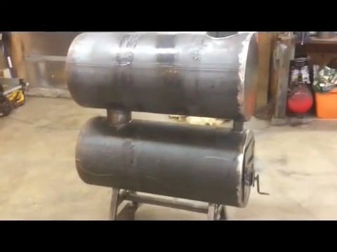
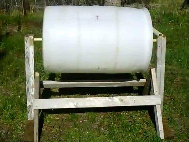
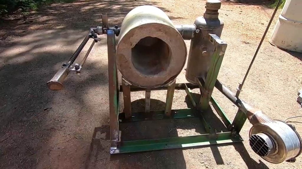
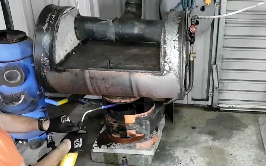
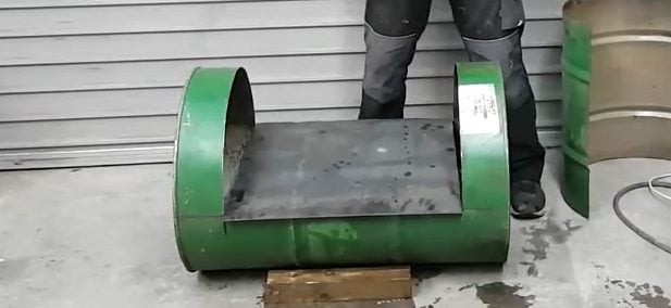
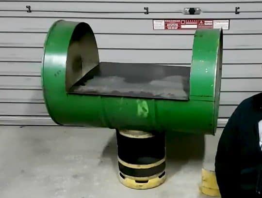
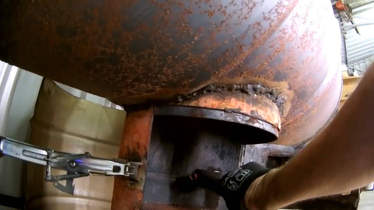
In this step, we focus on the installation of a 55-gallon drum to radiate the heat generated by the waste oil garage heater. The drum is placed over the propane tank burner unit, which acts as the heat source.
To construct the heat radiating drum, we take the 55-gallon drum and place it on its side. A portion of the drum is then cut out, creating a space for the burner unit to fit inside.
A steel plate is then placed in the middle of the drum, acting as a cooktop for the heating system. This cooktop is a useful addition, allowing for easy and convenient heating of small items while using the system.
On the other side of the drum, a hole is made to allow it to sit tightly on top of the propane burner tank.
STEP 5 : HEAT DISTRIBUTION AND FLUE PIPE
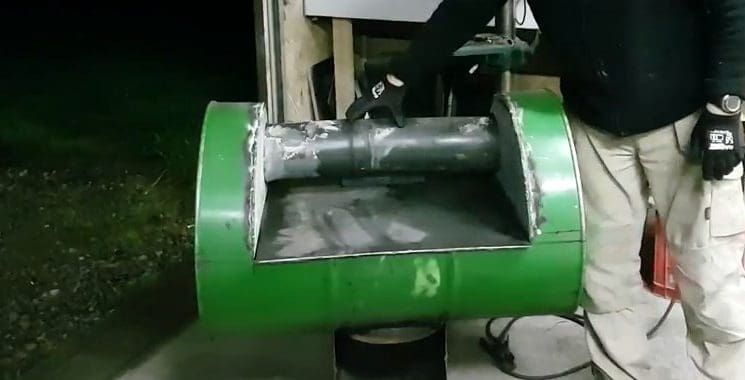
In this step, we focus on the installation of a heat distribution system for the waste oil garage heater. This system involves the use of a six-inch steel pipe welded onto the two upright sides of the 55-gallon drum.
This pipe is designed to distribute the heat generated by the burner unit throughout the workspace.
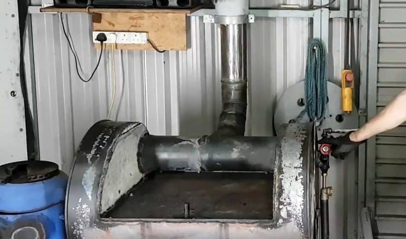
The steel pipe serves as suction for the flue pipe, which is welded onto the pipe in the middle. This design allows for the exhaust gas from the burner unit to travel up through the barrel and into the pipe, effectively distributing the heat throughout the workspace.
As the exhaust gas travels up through the barrel, it heats the plate above it, providing additional heat radiation to the workspace.
The distribution system ensures that the heat generated by the waste oil garage heater is efficiently distributed, creating a comfortable and warm working environment.
Finally, the flue pipe moves the exhaust gas out through the flue, preventing it from building up inside the workspace.
STEP 6 : DRIP FED OIL SYSTEM
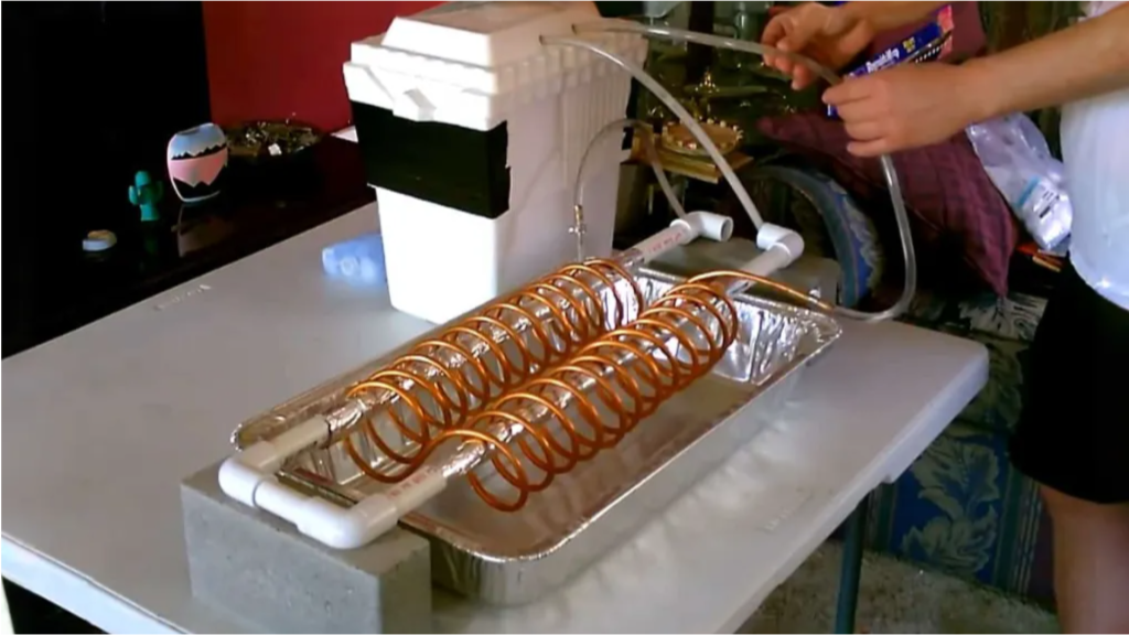
In order to effectively control the flow of waste oil into the burn chamber of the barrel stove, a drip feed system is used in this waste oil garage heater.
The drip feed system consists of several components that work together to regulate the amount of waste oil entering the burn chamber, ensuring that the system operates safely and efficiently.
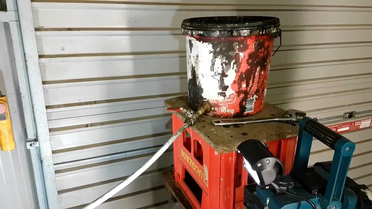
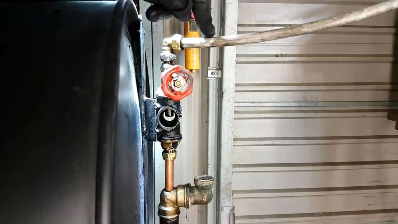
The drip feed system begins with a bucket used to store the waste oil. The oil is then connected to a half-inch pipe that features a ball valve for precise control over the flow of oil.
This pipe then connects to a standard half-inch gate valve, which serves as another point of control for the system.After passing through the gate valve, the pipe connects to a larger pipe within the system.
Within this larger pipe, a half-inch copper pipe is placed inside a one-inch mild steel pipe. This configuration allows for a more precise control of oil flow, which in turn improves the system’s efficiency.
The pipe coming from the gate valve is connected to the copper pipe inside the mild steel pipe through an elbow.
These two pipes then connect directly to the burner unit inside the propane tank. As a result, the waste oil is drip-fed into the candy tin of the burner unit, ensuring that the system can operate effectively and safely.
Once the waste oil garage heater is fully assembled, it’s time to start it up and begin enjoying its many benefits. To get started, the first step is to add some kerosene to the system. This is typically done by pouring the kerosene into the burner unit and lighting a fire using a torch.
Once the fire is lit, it’s important to allow the system to warm up gradually before adding waste oil. This allows the system to reach the desired operating temperature and ensures that it’s functioning properly before introducing the waste oil.
Once the system has warmed up sufficiently, it’s time to start the oil feed into the burn chamber. This is done by slowly opening the valve in the drip feed system.
As the waste oil begins to feed into the burn chamber, the system will start producing heat, which will radiate out into the surrounding space. Depending on the size of the space and the efficiency of the system, the waste oil garage heater can quickly and effectively warm up even large garages or other areas.
Image Credits : GerrysDiy