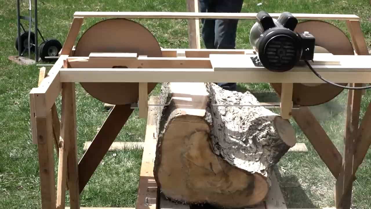
This project provides step-by-step instructions and helpful images to guide you through the construction process of creating a functional and cost-effective bandsaw mill that can turn hard maple into smaller lumber.
STEP 1 : MAKING THE WHEELS
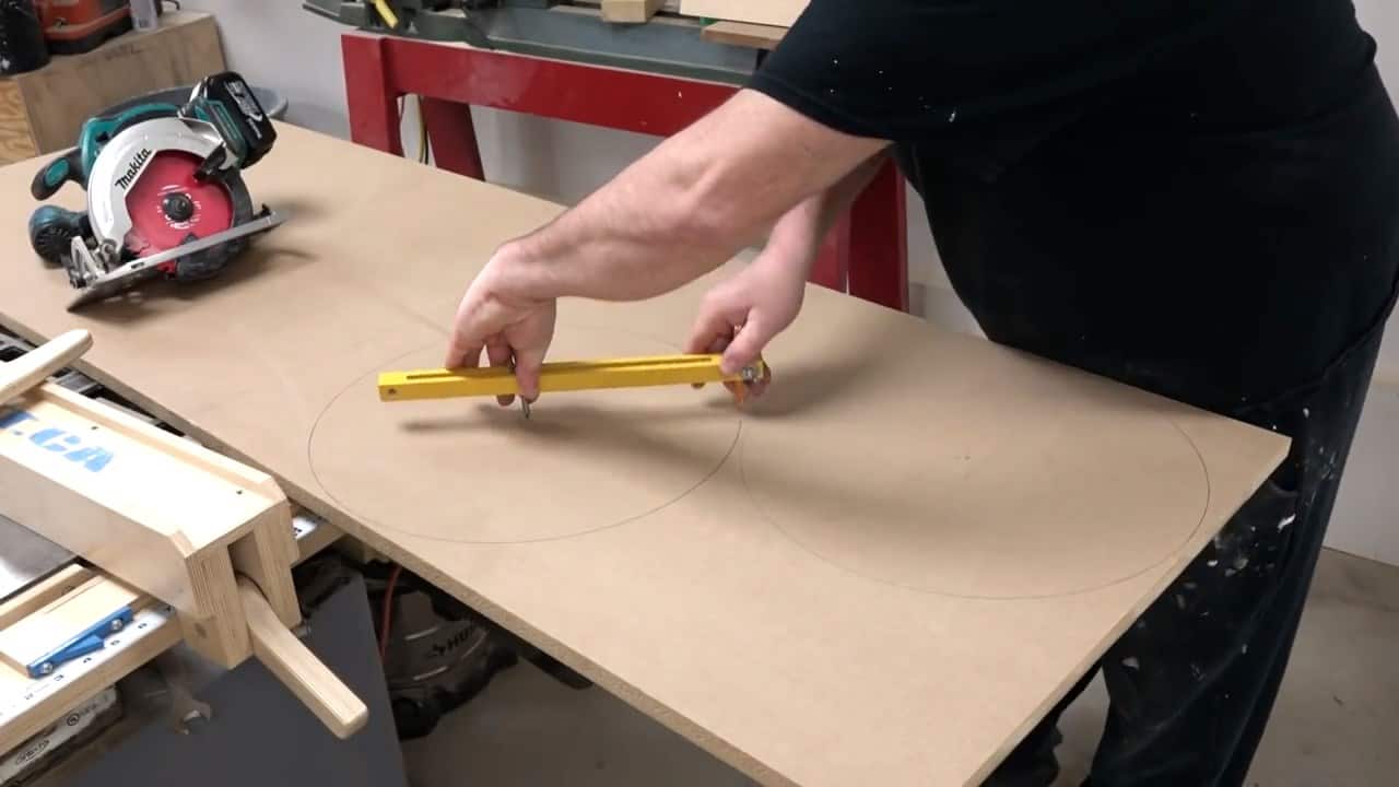
To begin the construction of your homemade bandsaw mill, the first step is to create the wheels.
For this purpose, we recommend using a 3/4 inch MDF board, as it is affordable and easy to work with. The size of the wheels should be around 16 inches in diameter.
To create the circular shape of the wheels, we suggest using a beam compass. This tool allows for precise circles to be drawn on the MDF board, making it easier to cut the circles out.
Once the circles have been drawn, use a saw to carefully cut out two identical wheels from the MDF board.
STEP 2 : ADDING PULLEY
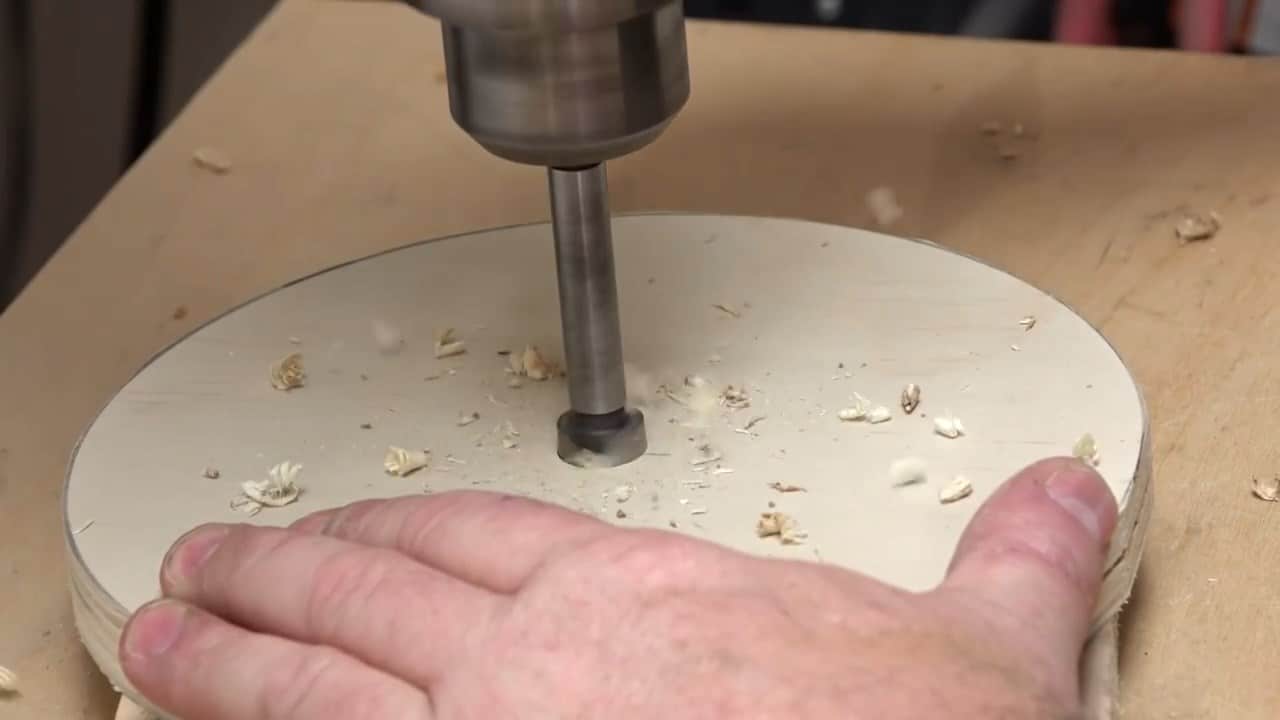
In order to drive the bandsaw blade effectively and precisely, the next step is to create a pulley for the wheel. For this purpose, we recommend using a three quarter inch plywood to create a pulley that is seven and a half inches in diameter.
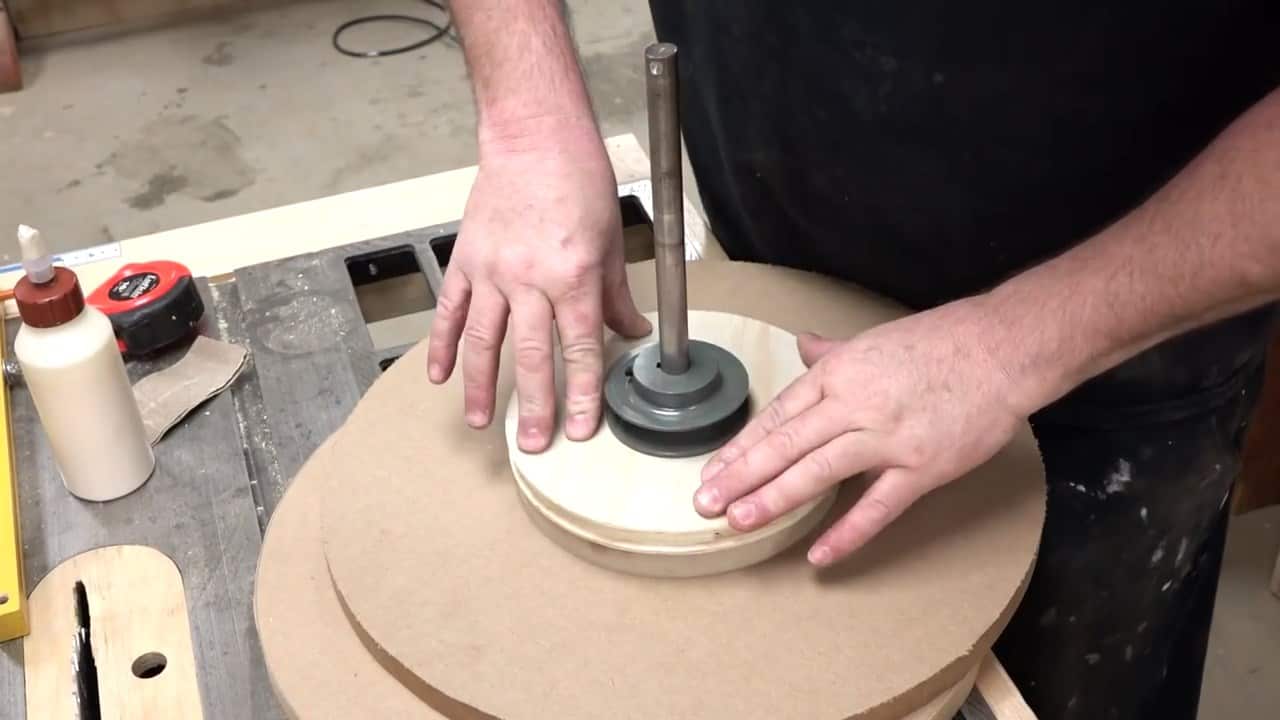
To create the pulley, drill a precise five-eighth inch hole in the center of the plywood where the shaft will go.
To prevent the pulley from spinning during use and to ensure a precise alignment with the bandsaw blade, the next step is to securely attach a stock collar onto the pulley.
To do this, apply hot melt glue onto the stock collar and then attach it onto the pulley. This strong adhesive will ensure a firm and permanent attachment of the collar onto the pulley.
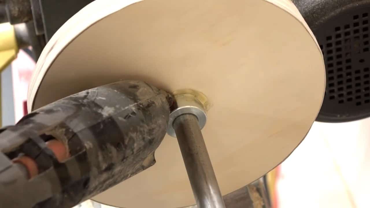
Before joining the wheel and pulley together, we make another small disc to go in between to act as a spacer.We glue the pulley to this spacer and from the spacer to the wheel.
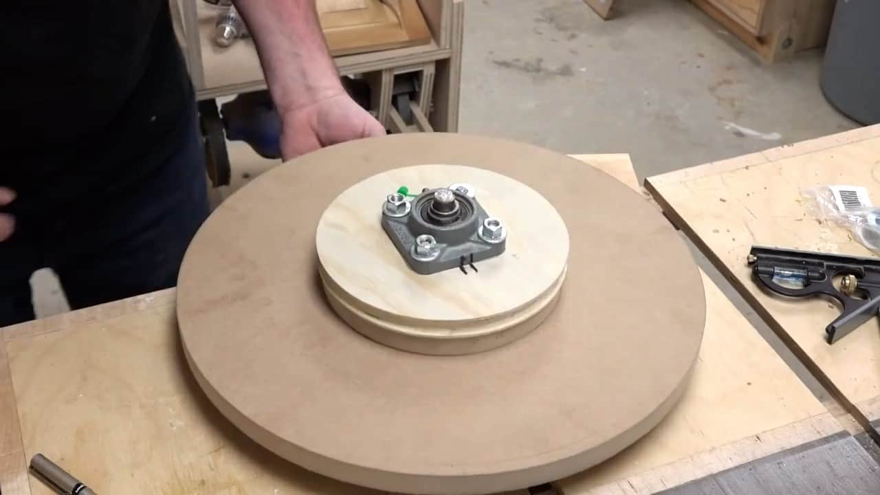
STEP 3 : ADDING WHEEL BEARING BLOCKS
Two-wheel bearing blocks are bolted to the wheel on both sides using 4 three eighth inch threaded rods. Make sure that the threaded rods are tight inside the hole in the wheel, but the bearing blocks themselves can move around.
One way to keep these bearing blocks in place so that they don’t move side to side is to apply some construction adhesive to the corners.
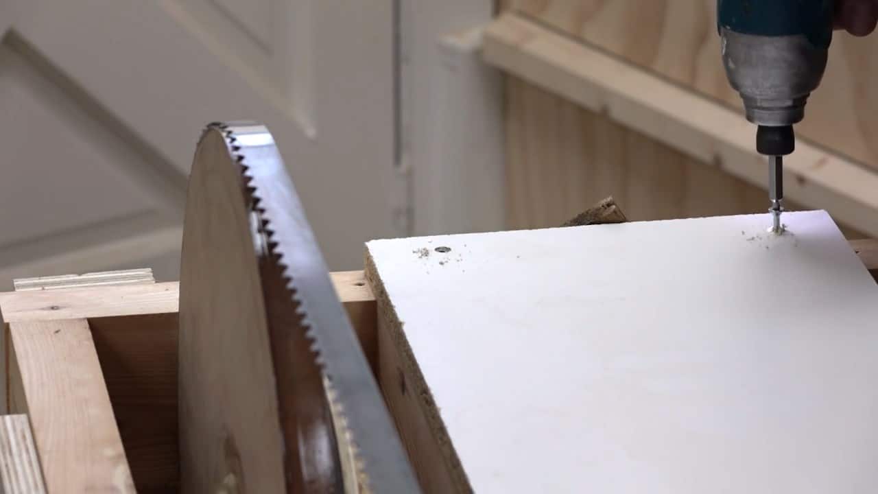
STEP 4 : BUILDING THE SAW FRAME
Now it’s time to move on to the frame for your homemade bandsaw mill. For this, we’ll be using salvaged 2 x 4 boards. It’s important to select boards that are straight and free of warping.
Once you’ve chosen your boards, it’s time to smooth out the edges using a bench hand plane. This will ensure that the boards sit flat and level.
Planing can take some time and patience, as you’ll need to make several shallow passes and flip the board each time to get rid of any twists or warps.
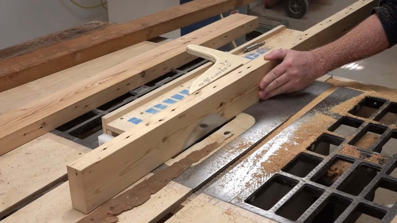
In the next step, we’ll be focusing on attaching the wheels to the frame. To do this, we’ll be using two frame pieces to hold the wheel in place. The stationary drive wheel should be placed 8.5 inches from the end of the frame.
We’ll need to drill two 5/8 inch holes on both frames so that the axles can fit in neatly. On the other side, we’ll drill one hole which will give us room to adjust the wheel.
To make these adjustments, we’ll create an adjustment collar out of plywood. This collar will be bolted into the frame and shaft, allowing us to adjust the position of the wheel.
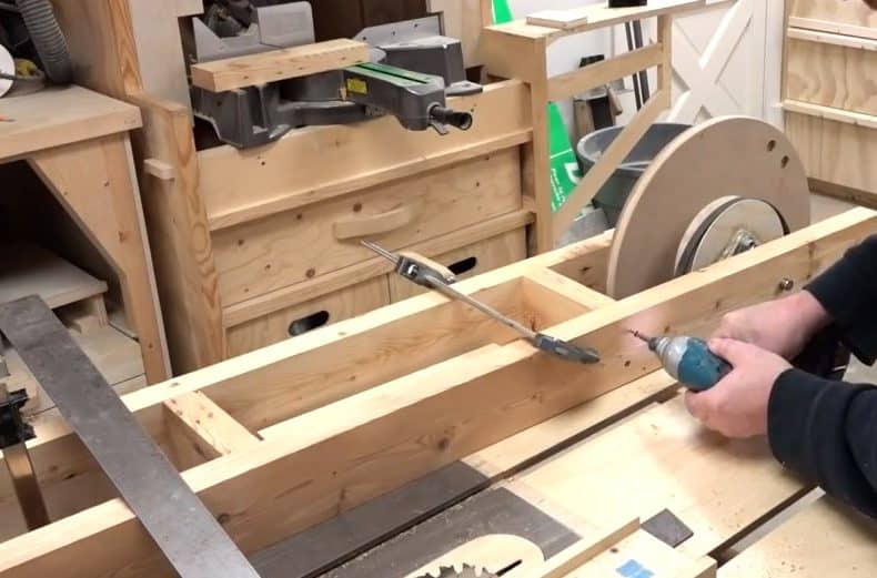
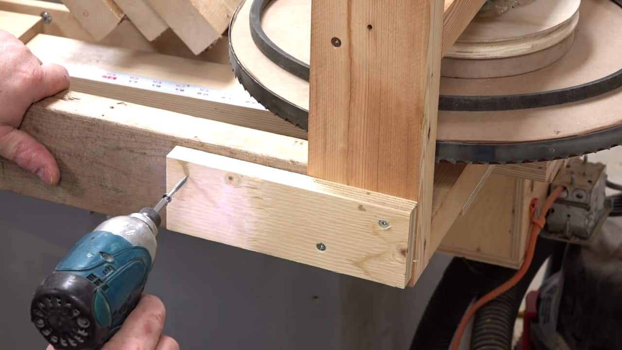
In addition to attaching the wheels to the frame, we need to secure the supporting boards tightly in position to prevent any unnecessary movement during operation.
To do this, we’ll add a couple of pieces across the frame, perpendicular to the supporting boards. These pieces will act as cross braces, helping to lock the supporting boards in place.
STEP 5 : INSTALLING THE FRONT WHEEL
Now, we’ll install the front wheel, also known as the top wheel. This wheel serves two critical functions in our homemade bandsaw mill.
First, it must be able to move back and forth to adjust the tension on the blade. Second, it must have a tracking mechanism to ensure the blade stays aligned during operation.
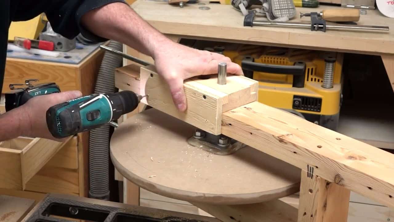
To create the necessary mechanism, we’ll make two small pieces that lock into the shaft on the front wheel and slide back and forth.
These pieces will allow us to adjust the position of the wheel and therefore the tension on the blade.
To guide the movement of the sliding pieces, we’ll drill a guide piece onto them.
This guide piece will ensure that the sliding pieces move in a straight line and prevent any unnecessary wobbling or misalignment.
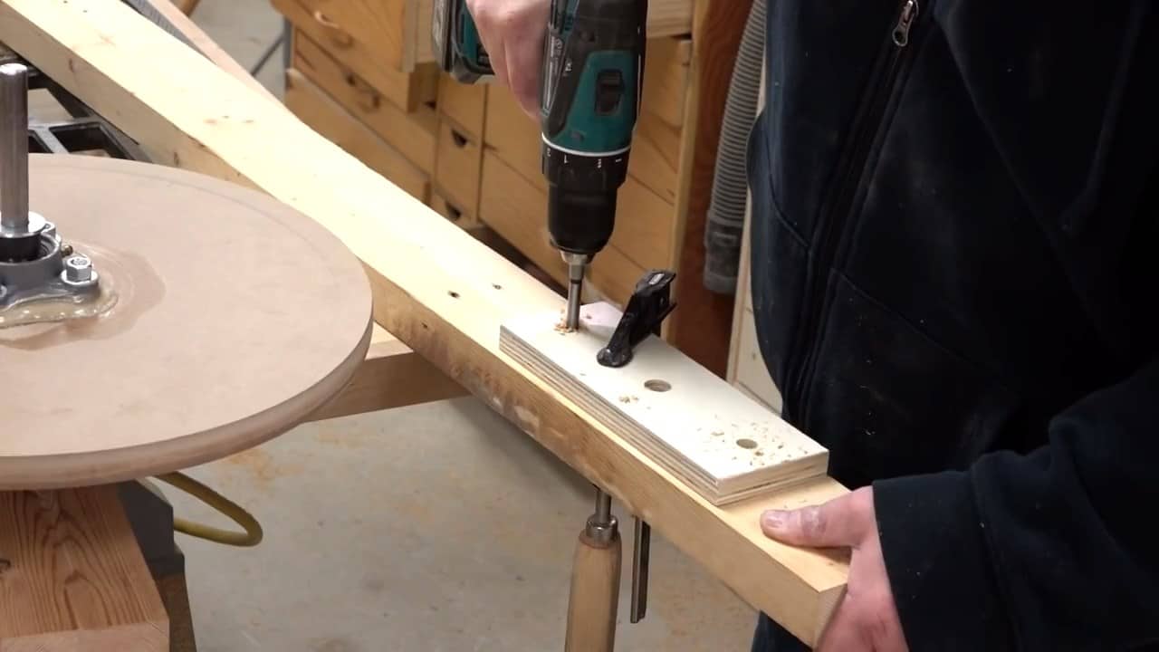
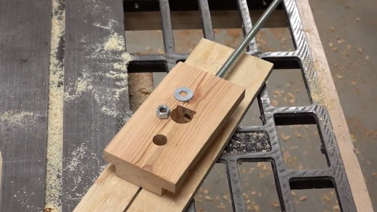
We’ll also drill a one-inch hole into our slider piece and secure a three-eighth inch threaded rod in it with a nut and washer.
These rods will help put tension on the blade and also allow us to adjust the tracking of the blade during operation.
![]()
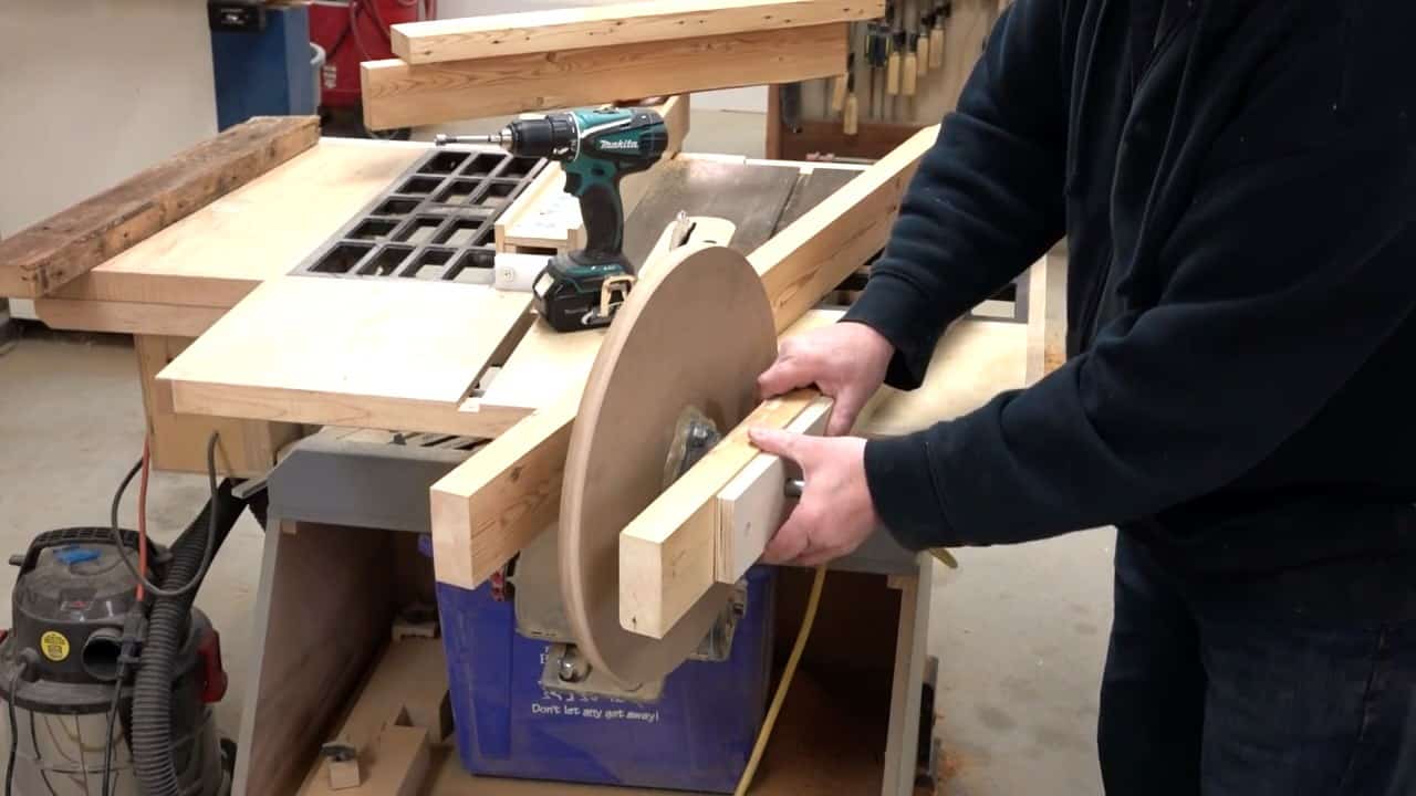
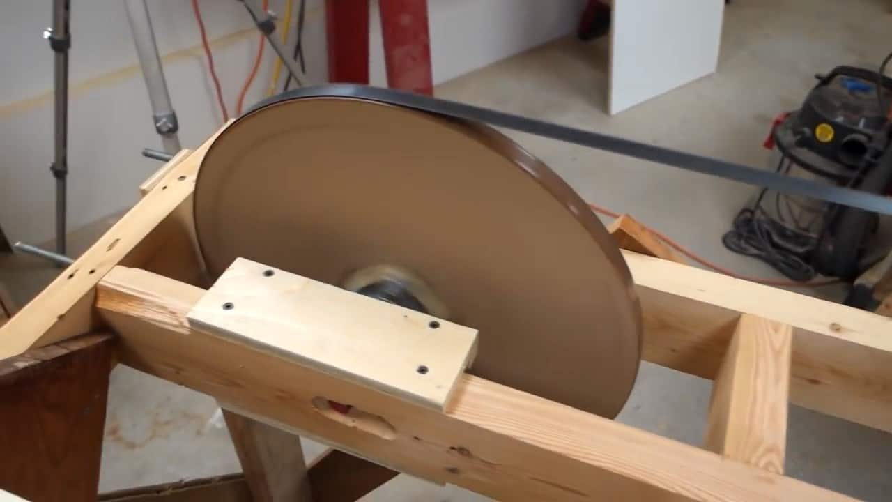
Before placing the blades on the wheels, it is essential to ensure that the wheels are perfectly smooth. To achieve this, we apply a layer of silicone caulking on the wheels.
This process helps to fill any gaps and smooth out the surfaces, which will prevent any unnecessary wear and tear on the blades.
This method has an advantage over using bicycle inner tubes as they tend to drape over the wheel surface, causing additional friction and reducing the overall efficiency of the mill.
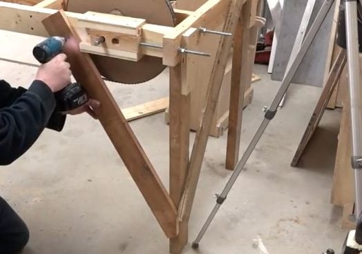
The next step involves attaching the legs to the frame using gusset blocks. These blocks are critical to ensure the stability of the mill during operation.
We recommend using sturdy and durable blocks made of either plywood or MDF board for this purpose.
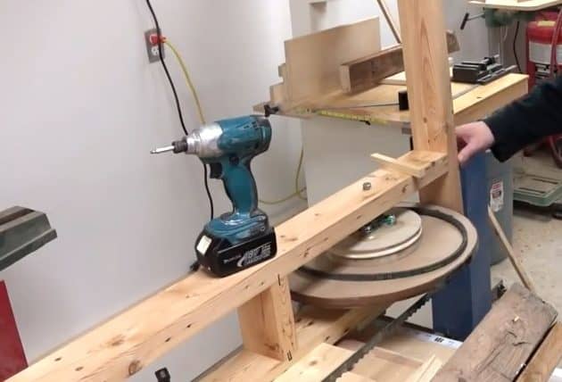
STEP 6 : MOUNTING THE MOTOR
To mount the motor onto the frame, we first take a sturdy melamine board and screw it to the side of the stationary wheel using an across board.
The melamine board not only provides support for the motor but also helps to brace up the top to prevent it from rocking during use. We make sure to secure the board tightly so that it resists any movement while cutting is in progress.
Once the board is securely in place, we attach the motor to it using screws and bolts, making sure that it is centered and level with the blade.
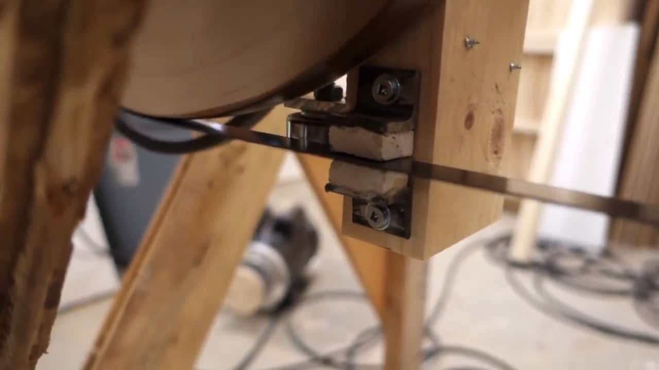
STEP 7 : ADDING BLADE GUIDES
For safety purposes, blade guides are installed near the bottom of the saw to prevent the blades from snapping and flying off. We use a small piece of steel angle and glue it to a ceramic piece to make the blade guides.
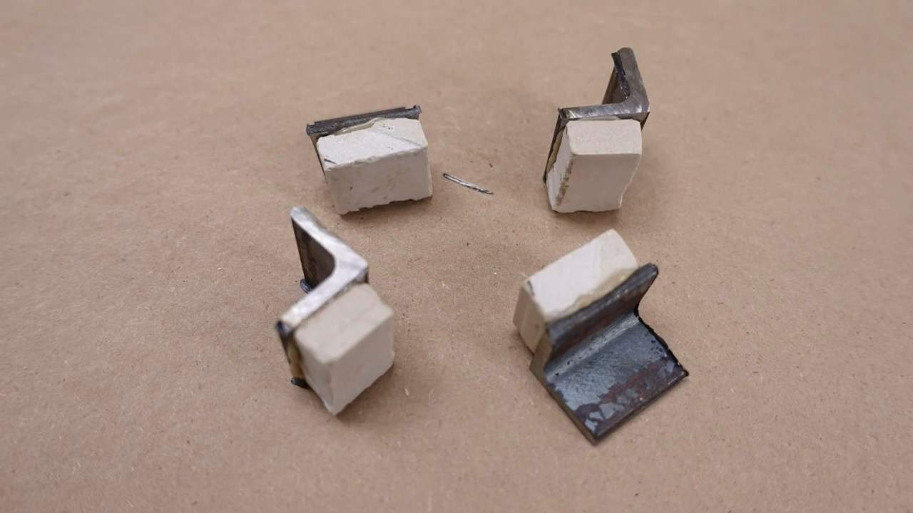
Blade guides play a crucial role in keeping the saw blade aligned and preventing it from twisting. They are designed in such a way that they do not make contact with the blade when it’s in motion.
Instead, they only constrain the blade’s movement if it tries to move up or down. This constraint ensures that the blade stays on track, reducing the risk of it snapping or flying off during operation.
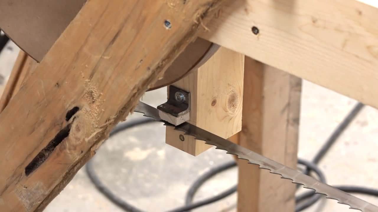
To prevent the blade from moving backward or forward, a thrust bearing made of regular size ball bearings is bolted onto an aluminum angle that is further attached to the blade guide.
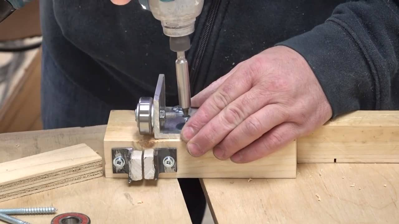
This thrust bearing not only helps to keep the blade on track but also reduces the heat generated due to friction between the blade and the blade guide.
STEP 8 : MAKING A DOLLY CART
To move the large maple logs through the blades, we construct a dolly cart using 2 X 4 boards and castors.
The castors are secured to the ends of the boards with quarter-inch holes and are positioned to move in a single direction. This makes it easy to move the logs through the blades with minimal effort.
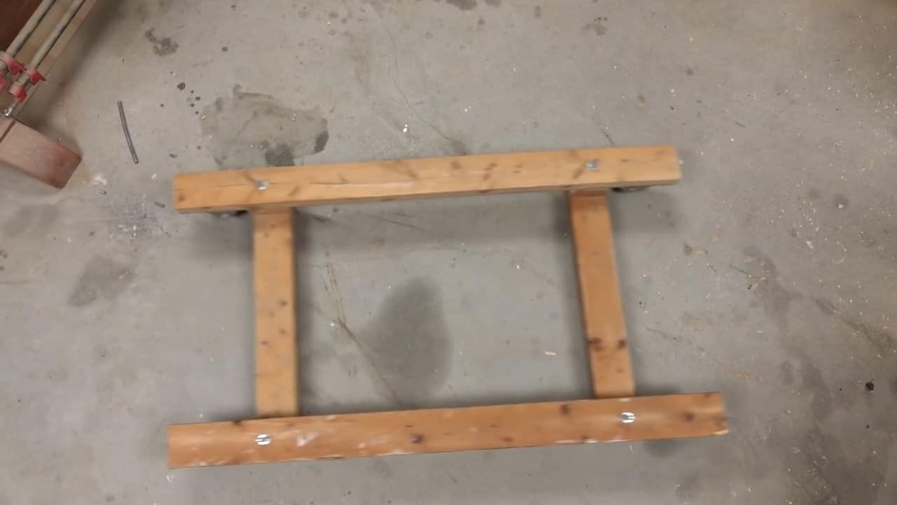
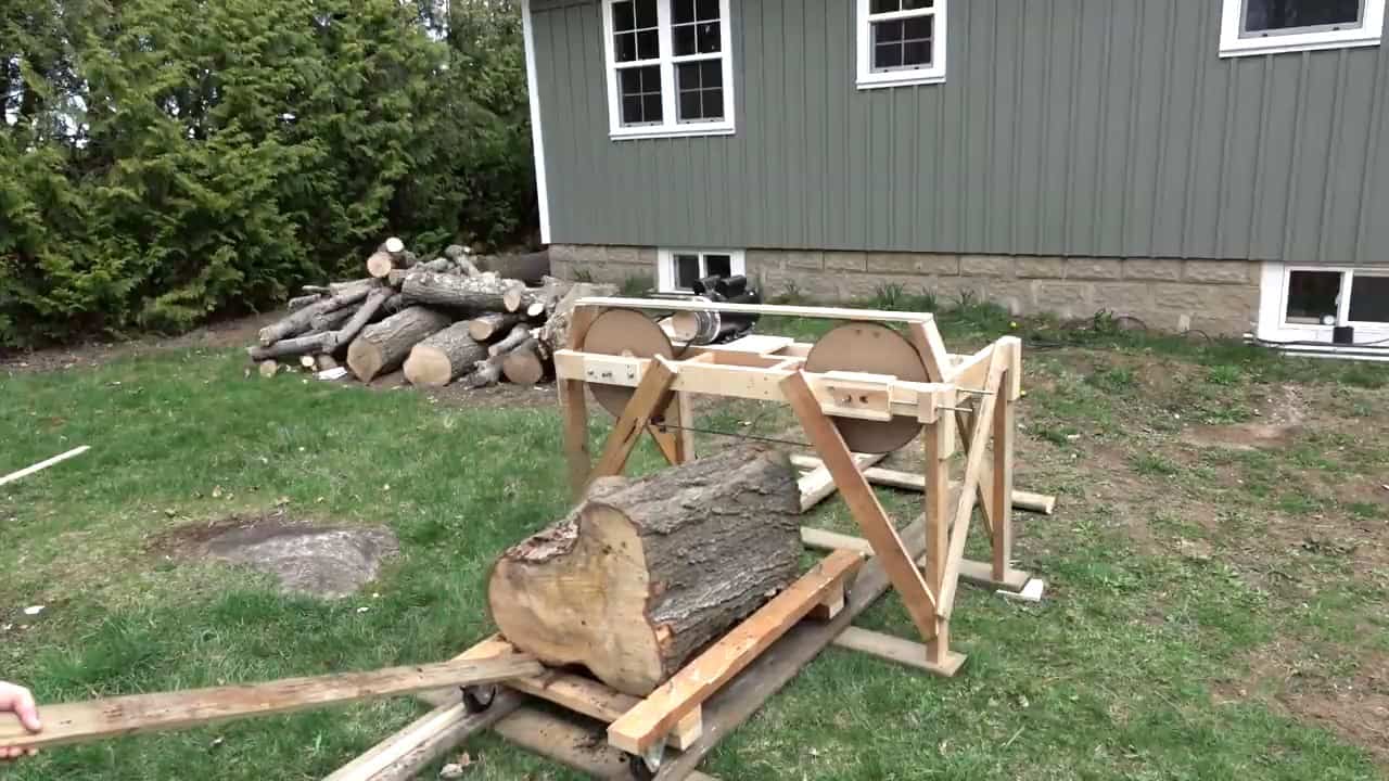
Image Credits : John Heisz – Speakers and Audio Projects