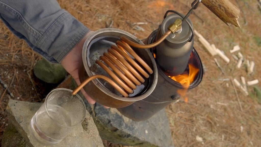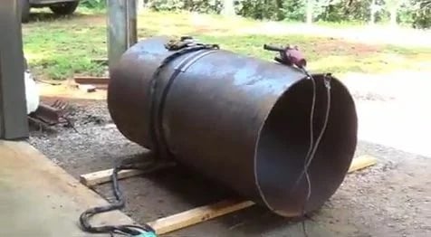
This article shows you how to build a high-efficiency rocket stove boiler that heats water for a shop or home, built from a scrap drum, a retired propane tank, copper coil, concrete, and vermiculite.A rocket stove boiler is a wood-fired heater that uses a rocket-style burn chamber to drive heat through copper coils, producing hot water with little smoke and very little fuel.
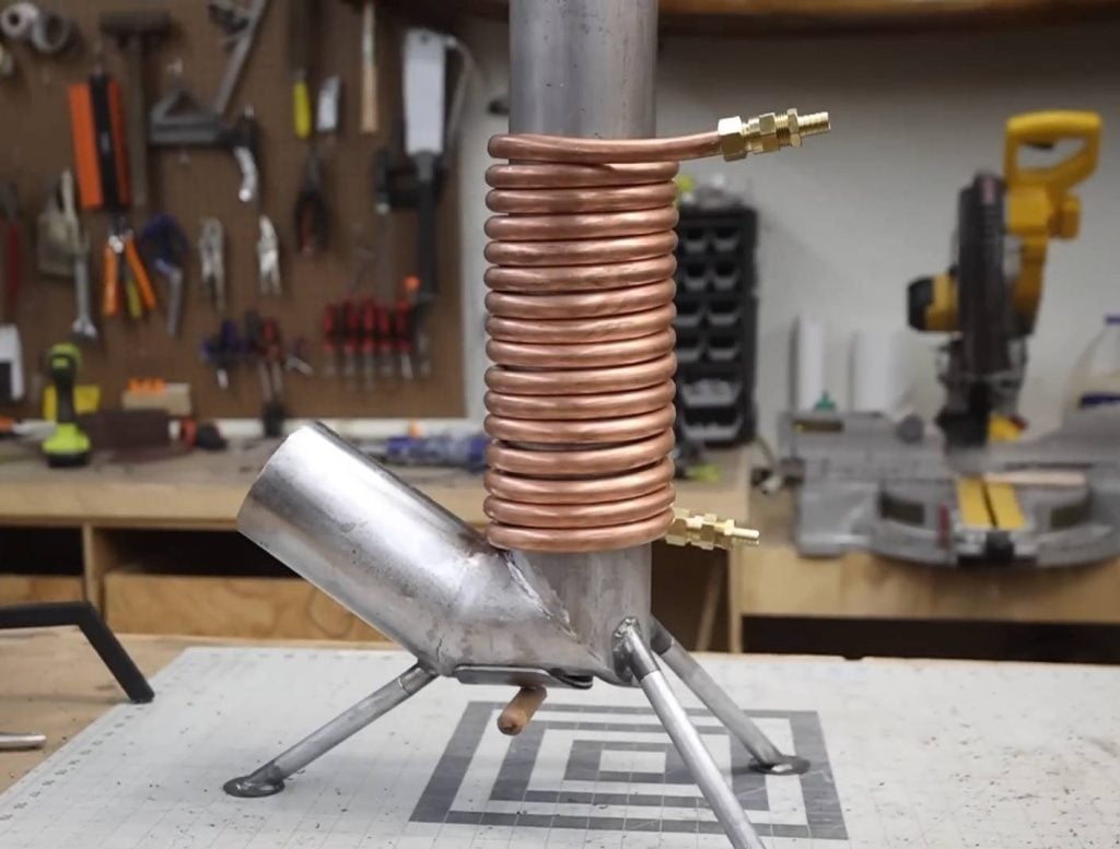
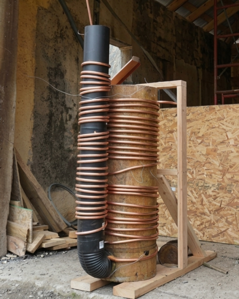
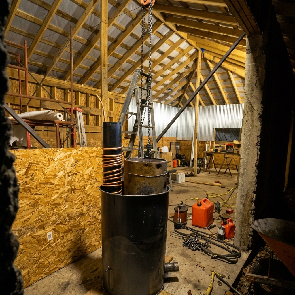
The core is a propane tank burn chamber connected to a 6-inch stove pipe riser, with 1/2-inch copper coil wrapped around both as the heat exchanger. That entire assembly sits inside a 55-gallon drum, which is then locked together with concrete at the base and packed with vermiculite for insulation.
Step 1 : The Materials Required
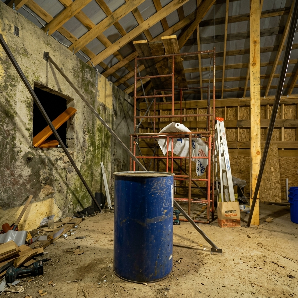
- 1 x 55-gallon steel drum (the outer shell)
- 1 x retired propane tank (the burn chamber), valve removed
- 1 x 6-inch stove pipe (the riser tube) plus a corrugated 6-inch elbow
- 1/2-inch OD soft copper tubing (the heat exchangers)
- Concrete mix (base)
- Vermiculite (insulation)
- 1/2-inch brass flare nuts and a flare union
- Antifreeze (for the water loop)
- Tie wire
- Plasma cutter, angle grinder, drill, hammer, metal snips
- Tubing cutter and flaring tool
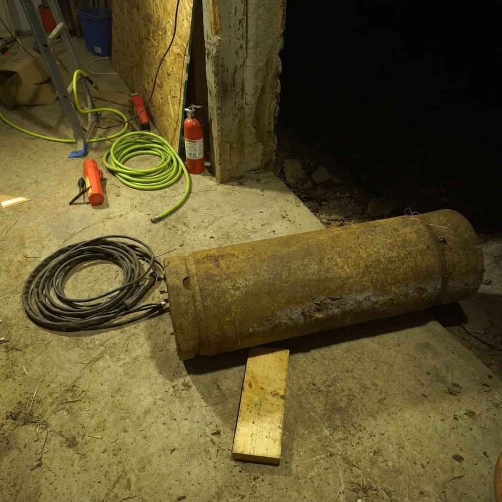
An empty tank that has had its valve out for a long time is safe to cut. If the tank is more recent or you aren’t certain, fill it completely with water first; the water displaces any remaining gas and makes it safe. 3/4-inch copper is too stiff to bend tightly and gives too little metal-to-water ratio for good heat transfer. Half-inch OD is the right size for this build.
Step 2 : Cut the Propane Tank
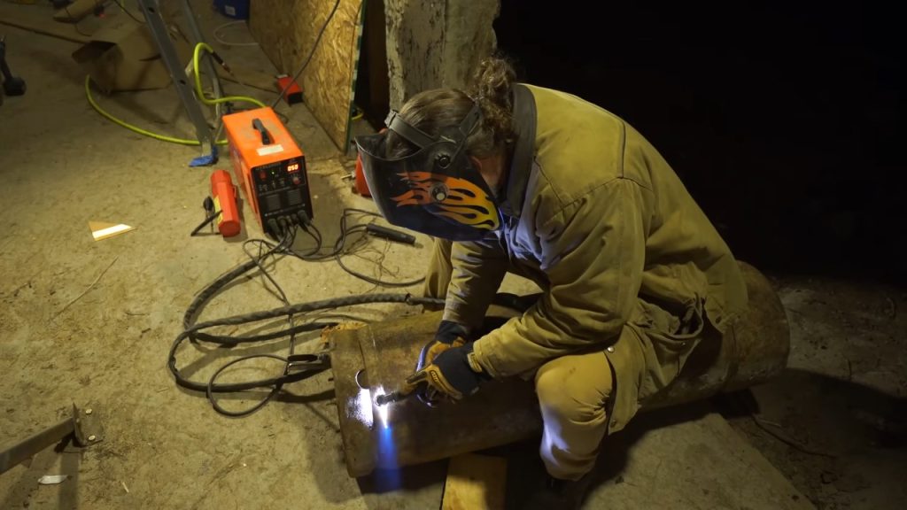
Mark the tank and cut it along the seam just past the weld, where the metal is thinner. This gives you two pieces: the tank body becomes your burn chamber, and the severed end is set aside. The builder planned to invert it into a lid, though he later found the stove may not need one.Work with a plasma cutter for speed and clean edges, and keep your hands clear of the cut line.
Step 3: Cut the Riser Outlet
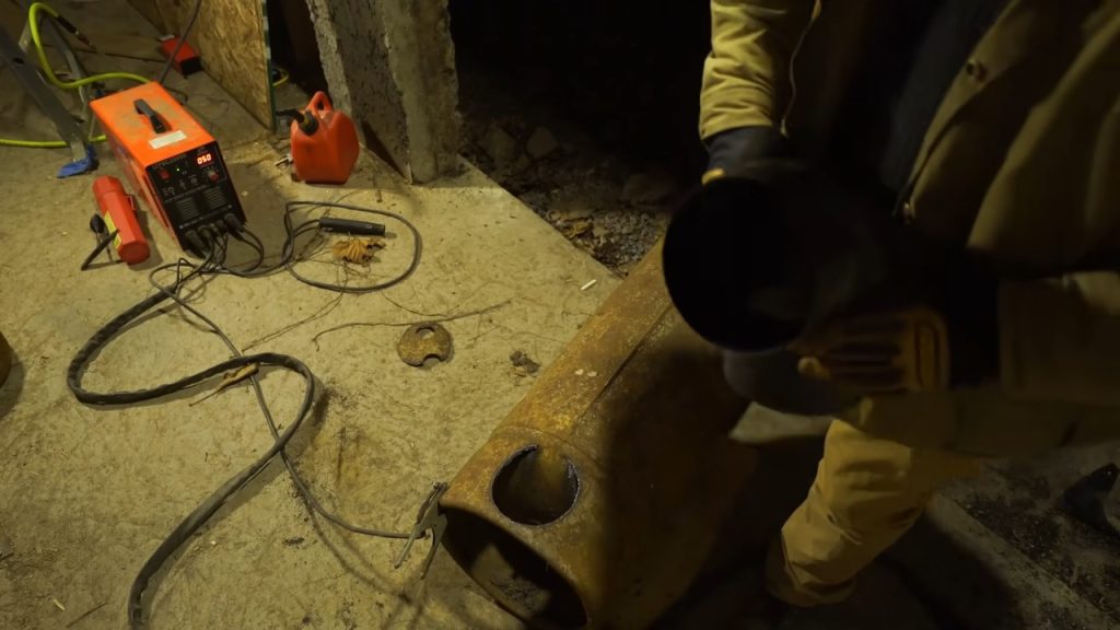
Set the 6-inch elbow against the tank where the riser will exit, trace its outline all the way around, and cut that opening out.
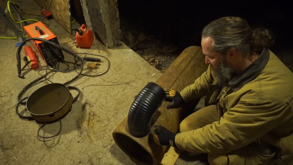
Cut this opening tight. A snug friction fit is far better than a loose one; you can always persuade a tight joint with a hammer, but you can’t easily fix a gap. 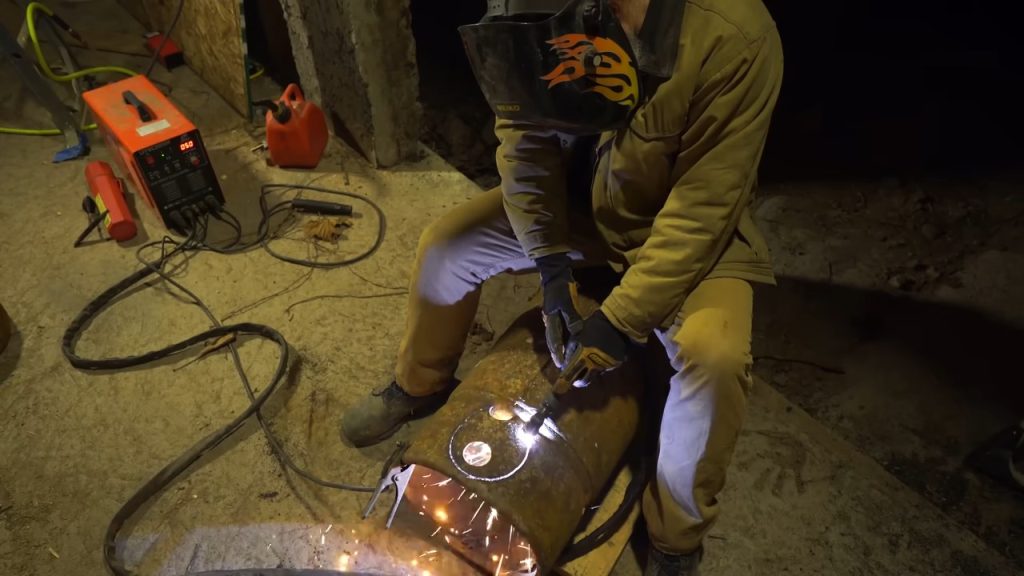
Take care not to cut into the structural shoulder of the tank while you’re working around the curve.
Step 4 : Cut the Ash Grate
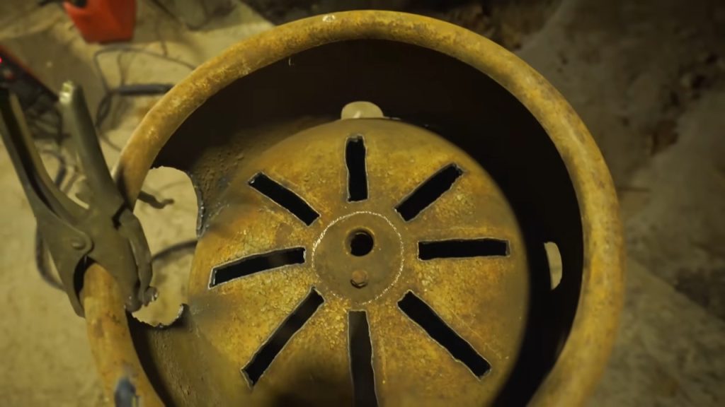
Lay out a spoke pattern radiating from the center hole and cut slots along those lines. A symmetrical pattern is easier to cut cleanly with a plasma cutter than a freehand one.
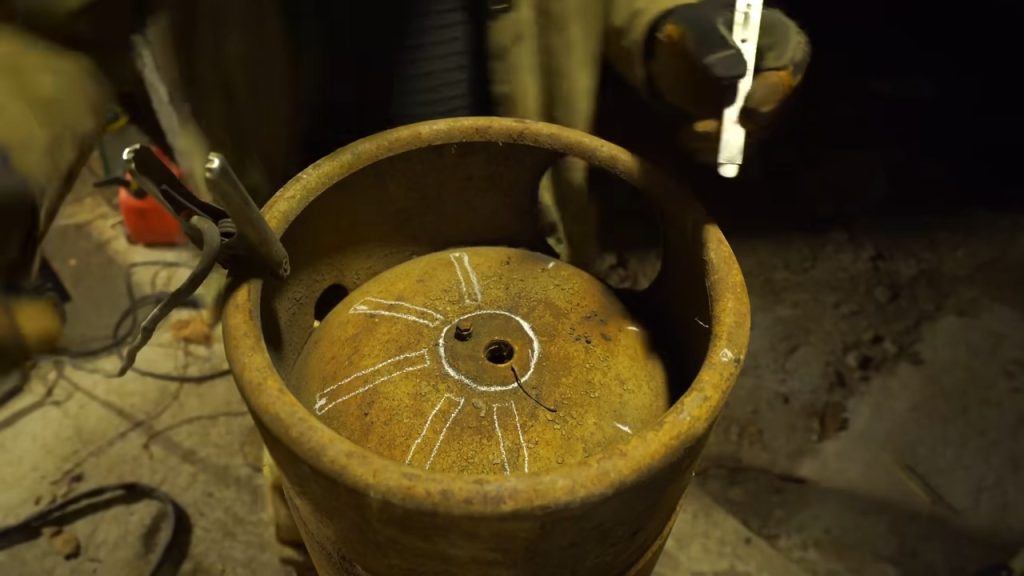
The slots need to let ash drop through while still supporting the burning fuel. The builder’s version-one grate used wide openings and ash dropped through with no problem; this version keeps a symmetrical spoke layout mainly because it’s faster to cut with the plasma cutter.
Step 5 : Notch and Fit the Riser Elbow
Because the tank is curved, the crimped end of the elbow has to be notched to sit flush against the contour. Cut slits about every half inch to 5/8 inch along the crimp, then fold the resulting tabs outward with a hammer to form a flange that holds the elbow in the opening.
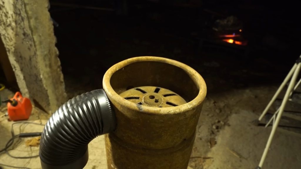
This part is eyeball work: test-fit, adjust, and repeat until the elbow sits right.
Step 6 : Check Drum Clearance
The combined diameter of the burn chamber and the attached riser has to fit inside the drum. On the builder’s drum that’s about 22 inches of clearance.
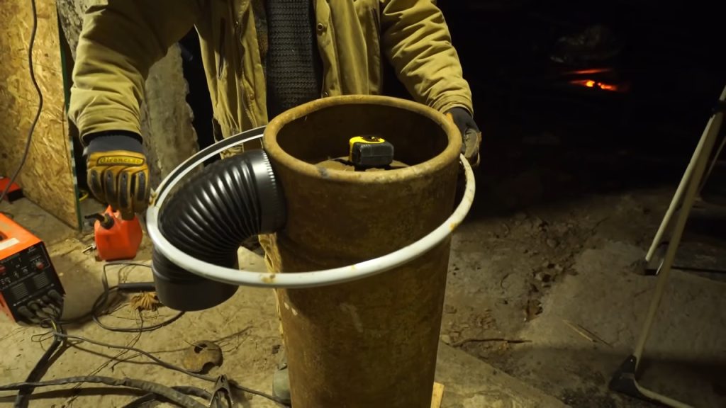
If the assembly is too wide, trim the elbow back (continuing its existing crimp) so it drives further into the tank. Getting the riser plumb matters here too, so the stove pipe runs straight rather than cocked to one side.
Step 7 : Fill and Freeze the Copper Tubing
Before bending, the copper has to be supported from the inside or it will kink and flatten. Push a garden hose onto one end and run water through until it sprays solid out the far end; that purges all the air. Then cap both ends and freeze the coil.
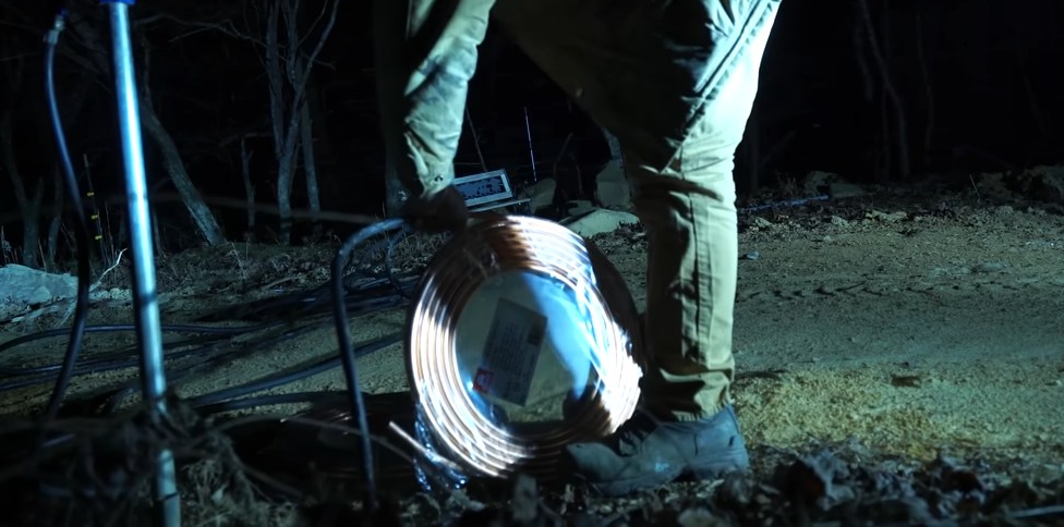
Freezing works overnight if you’re building in winter; otherwise use a freezer. The ice fills the tube and holds the walls round while you bend it.
Step 8 : Weld the Elbow to the Burn Chamber
With the elbow fitted and plumb, wire it in position and tack-weld it to the tank. The tabs bent up in the fit hold it while you strike the arc.
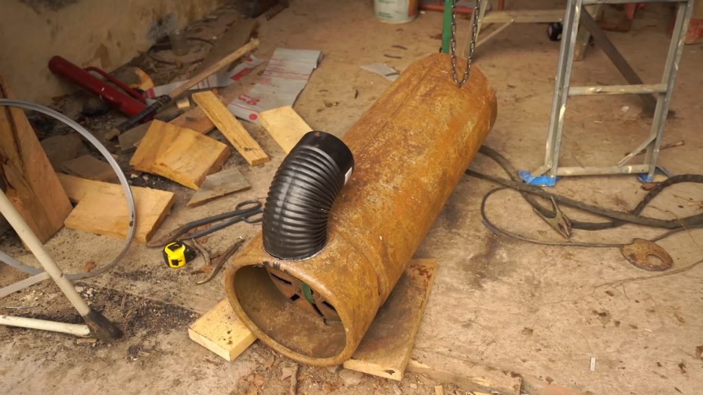
Everything above this joint is going to be locked in concrete later, so this is a positioning weld, not a structural one; it just needs to hold the geometry and stay aligned.
Step 9 : Grind the Tank Weld Seam
The propane tank has a raised, sharp factory weld seam running around it. Grind that flush.
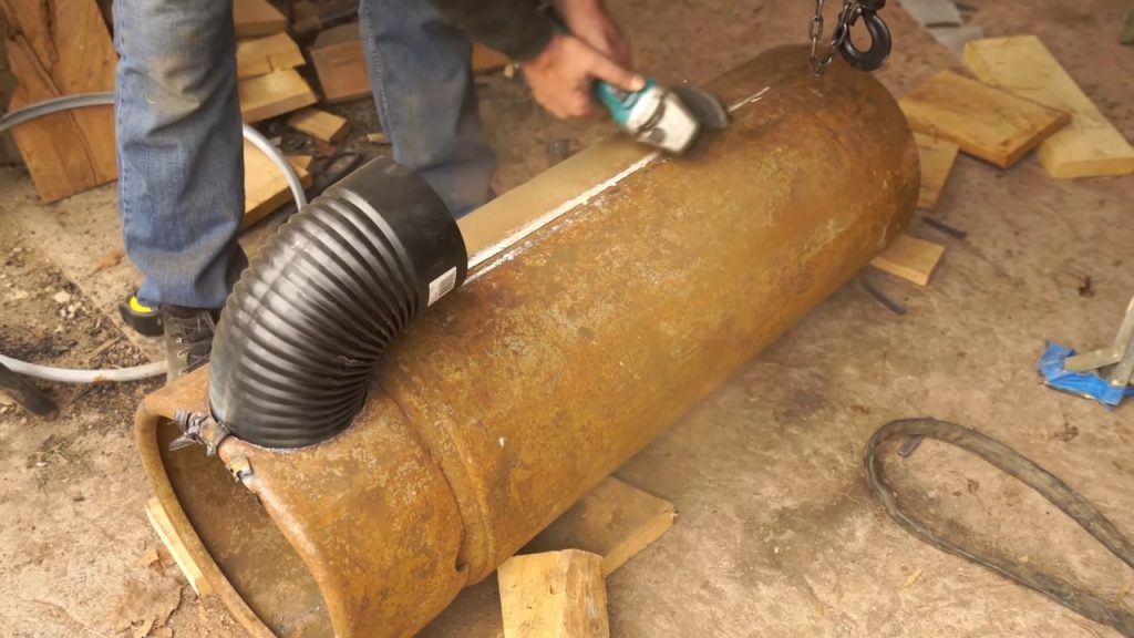
The copper coil gets wrapped directly over this surface, and a sharp ridge will abrade or eventually puncture the tubing as the metals expand and contract against each other.
Step 10: Wrap the Burn Chamber Heat Exchanger
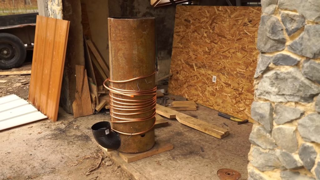
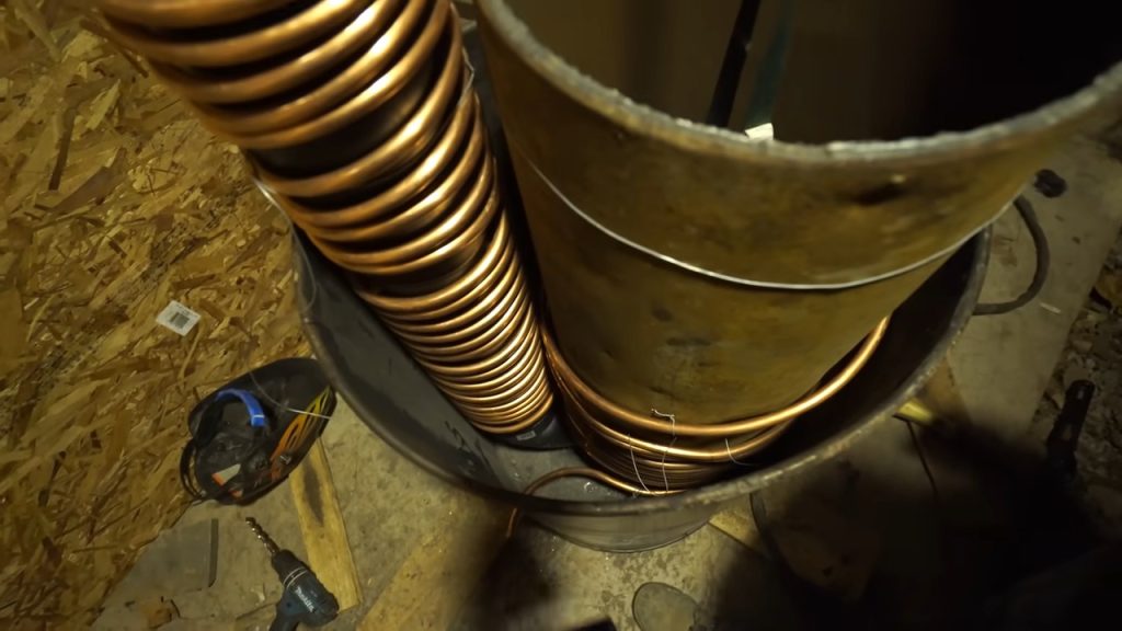
Working quickly before the ice thaws, wrap the frozen copper tightly around the burn chamber body. Anchor each turn with tie wire as you go so the coil doesn’t spring back.
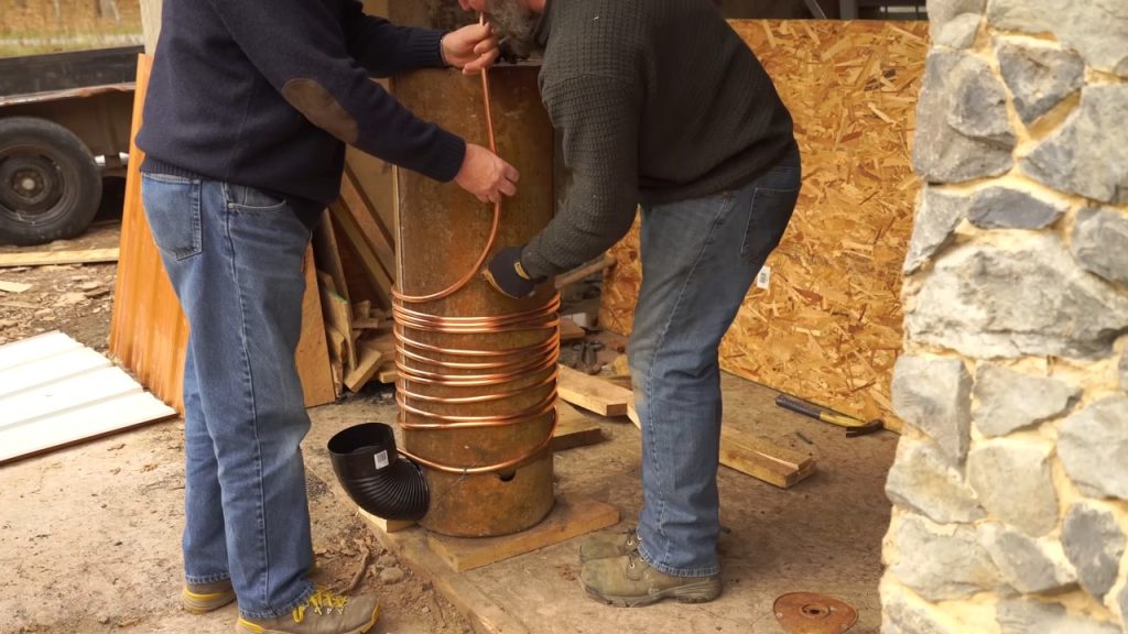
Leave clearance between the coil and where the drum wall will sit; the coil should not make contact with the outer steel.
Step 11: Wrap the Riser Tube Heat Exchanger
Wind a second length of frozen copper around the 6-inch riser pipe, forming a helix that runs up its length. The riser carries the hottest flue gases, so this is where you capture much of the heat.
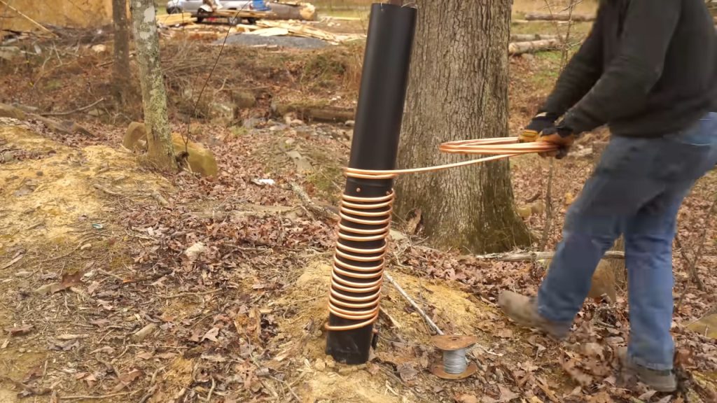
You don’t need to coil the full height; roughly a third to half of the riser is enough.
Step 12 : Mount the Riser onto the Burn Chamber
Seat the riser into the elbow and secure it upright against the burn chamber, using wire to hold it in position.
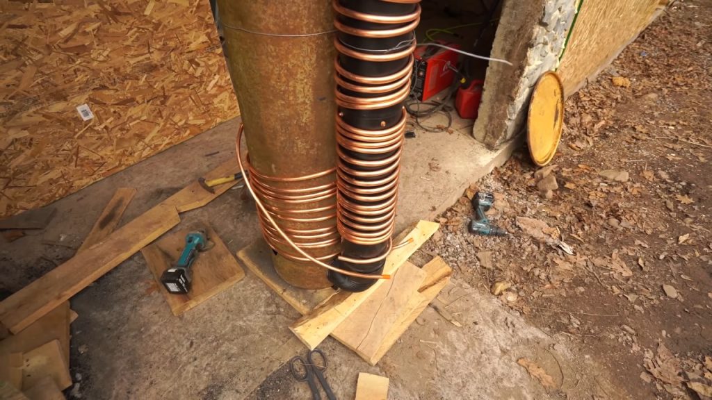
Everything gets locked into place with concrete shortly, so this is a temporary hold, but the riser needs to be stable and true before you pour.
Step 13 : Flare and Connect the Coils
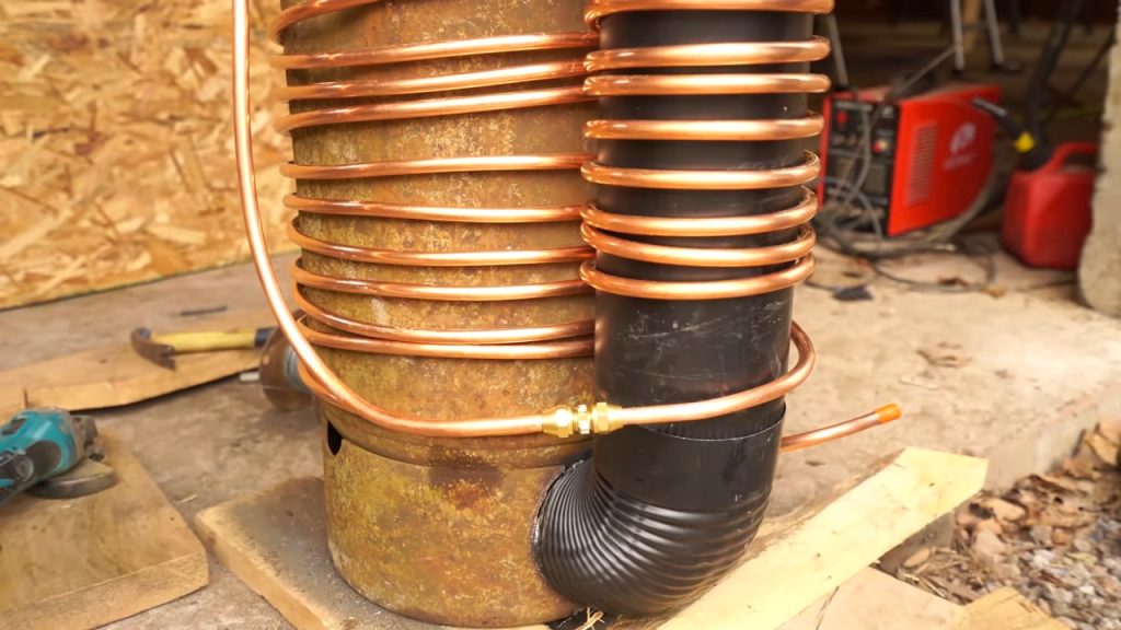
Using flare fittings rather than rubber hose means the connection between the two heat exchangers stays inside the stove body. Bringing hot water outside the stove to a rubber joint loses efficiency, so keeping the joint internal is worth the extra effort.
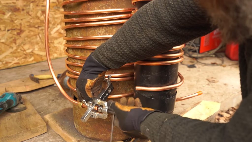
Cut the tubing ends square, install the flare nuts, flare the copper, and join the burn chamber coil to the riser coil with a flare union (part #75442 D08 / FLF-7402 half-union; the 1/2-inch brass flare nuts are Watts A-26C). This makes a metal-to-metal, watertight seal with no solder and no rubber in the hot zone.
Step 14: Dry-Fit the Core into the Drum
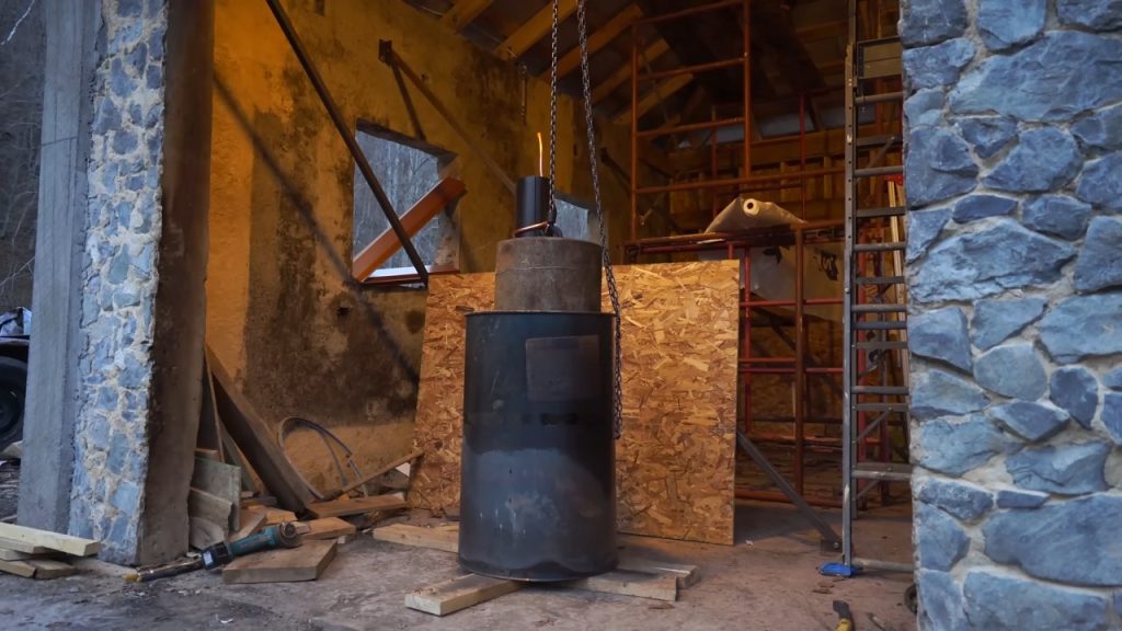
Lower the assembled core into the 55-gallon drum and check the fit before anything permanent happens.
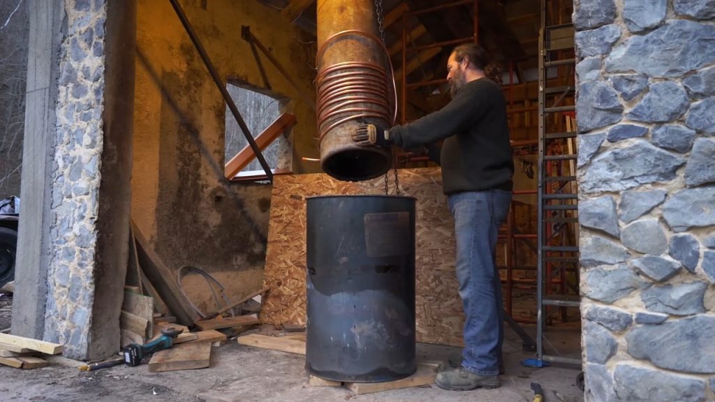
Check that the coiled assembly clears the drum wall and that the riser protrudes from the top as intended. The copper ends also need to reach the pass-through points.
Step15 :Cut the Air Inlet
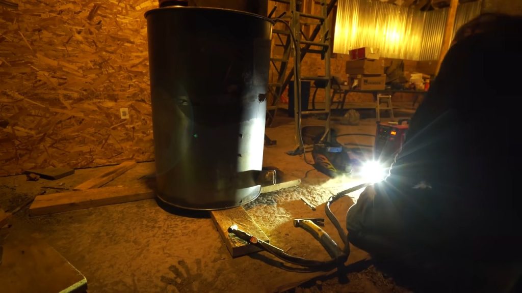
Drill a starting hole through the lower drum wall and cut out the inlet opening. Cut an internal lip or tongue in the opening and fold it inward so it deflects incoming air upward into the base of the fire.
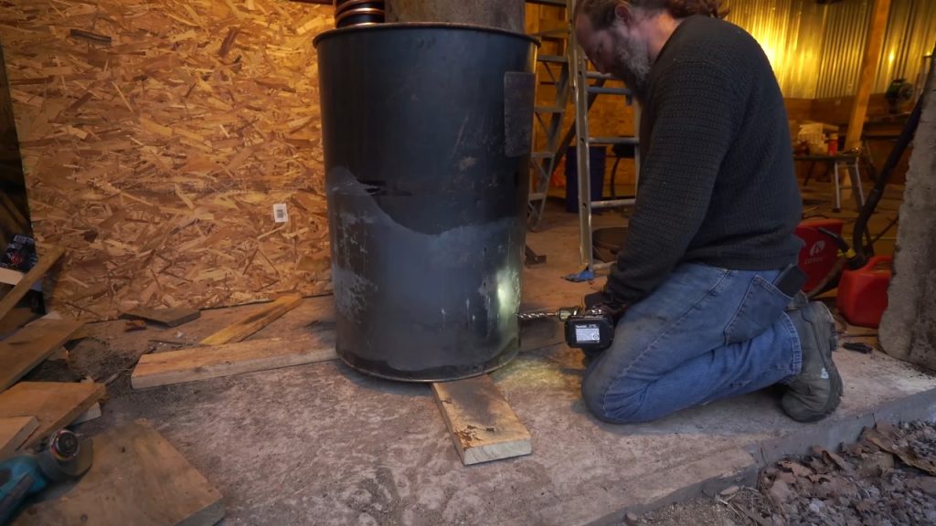
Directing this air at the coal bed rather than letting it simply leak in is the intent, though the builder had not yet proven how well a single inlet would work, and was ready to fall back to the 45-degree inlet he used on the first stove.
Step 16 : Drill the Plumbing Pass-Through
Drill a hole near the base of the drum for the cold-water inlet copper line to exit, and route the coil ends out through the barrel wall.
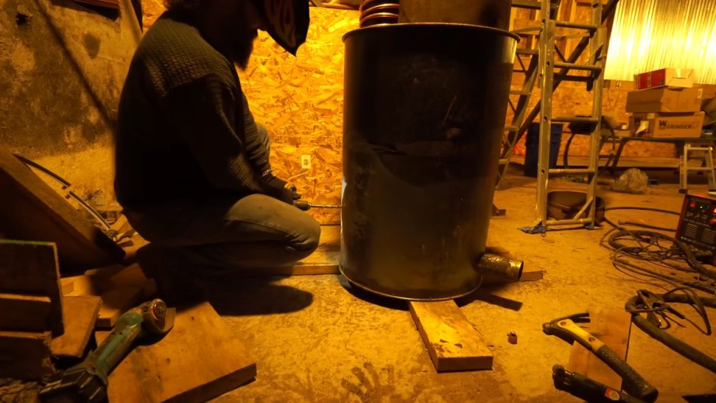
Step back and confirm clearance and alignment one more time before the concrete goes in; once it sets, none of this is adjustable.
Step 17 : Pour and Settle the Concrete Base
Pour concrete into the bottom of the drum, around the elbow and the tank base, to lock the whole assembly in place and seal it against air and smoke leaks. Fill so the concrete encases the base components.
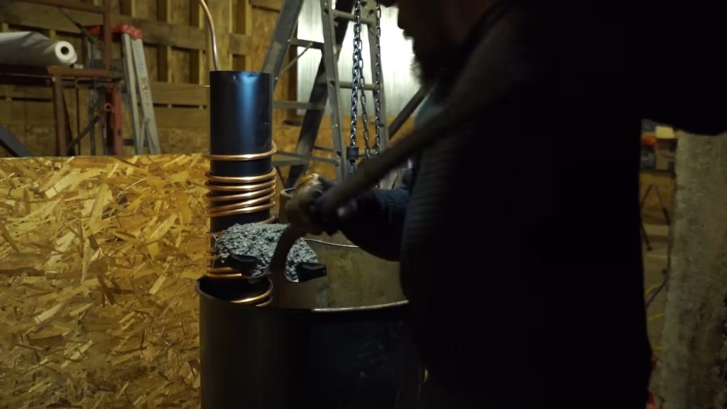
Then tap the outside of the barrel repeatedly with a mallet or block. The concrete will settle and wiggle as the voids work out; keep tapping until it stops settling. This vibration drives out the air pockets and prevents gaps that would otherwise become leaks.
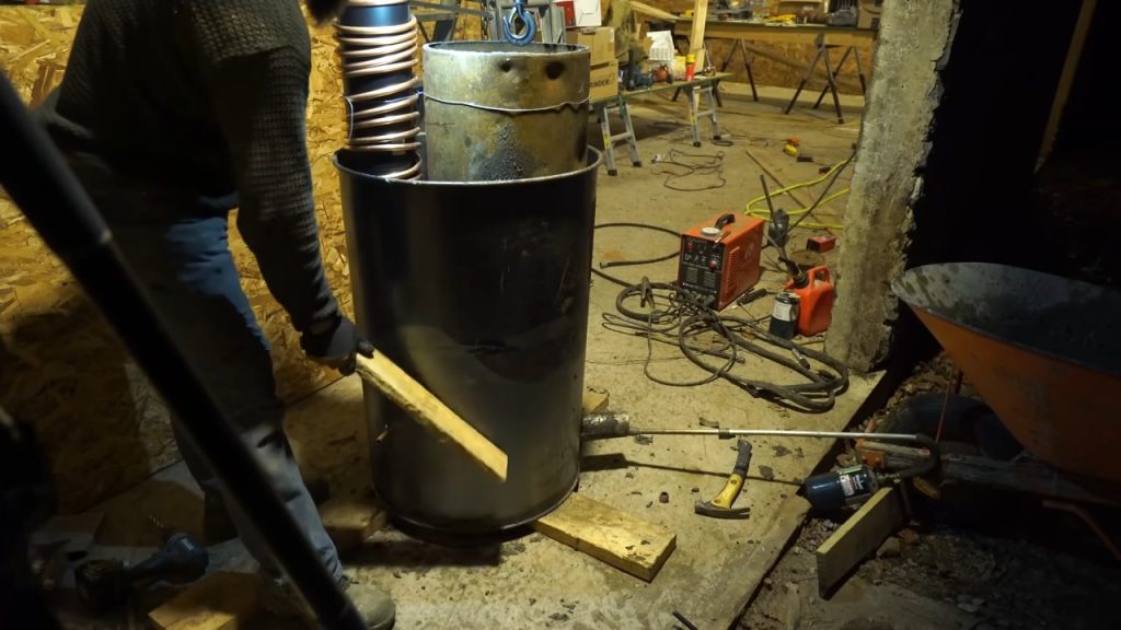
With the base poured, the next step is to pack vermiculite into the drum around the burn chamber and riser. Vermiculite insulates the whole core, which keeps the combustion zone superheated and improves the stove’s overall efficiency. Other than fuel going in and exhaust gases coming out, the entire core is sealed inside the single drum.
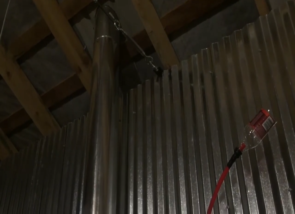
Then hook up the plumbing. Mix antifreeze roughly half and half with water, especially if the stove won’t run continuously through the winter and the loop could freeze. Start with a moderate volume and size the water to the system so you aren’t driving it into steam.
Finally, cure the concrete slowly. Running a small fire in the stove keeps the base from freezing while it cures.
Image Credits : midevilone / Timothy Luce