The aim of this project is to repurpose old and used laptop batteries, along with a military surplus box, to construct a backup battery system with a capacity of 1.72kWh.
By utilizing discarded laptop batteries, this project promotes sustainable and eco-friendly practices while providing a cost-effective solution for backup power needs.
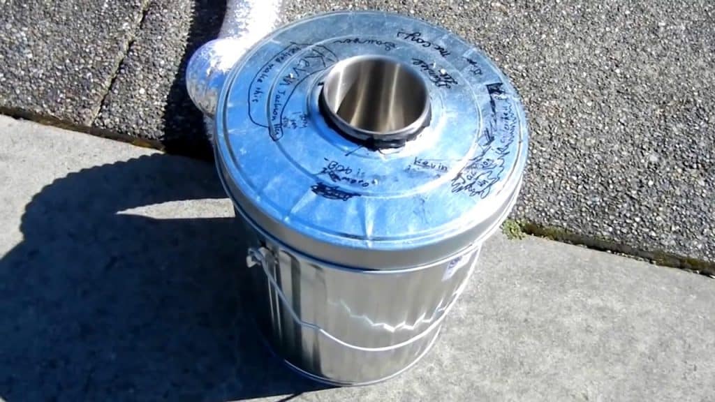
The military surplus box ensures durability and portability, making it an ideal choice for outdoor and emergency situations.
STEP 1 : MATERIALS REQUIRED
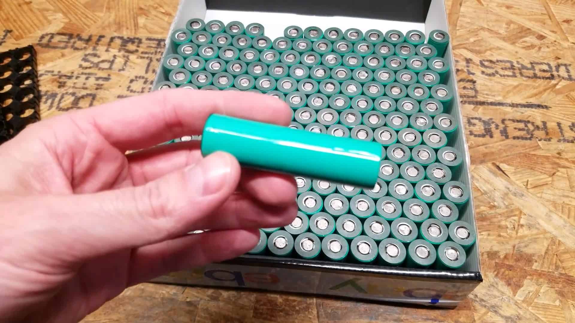
To complete this project, you will need a few key materials. First, you will need to source lithium-ion 18650 batteries from old laptops.
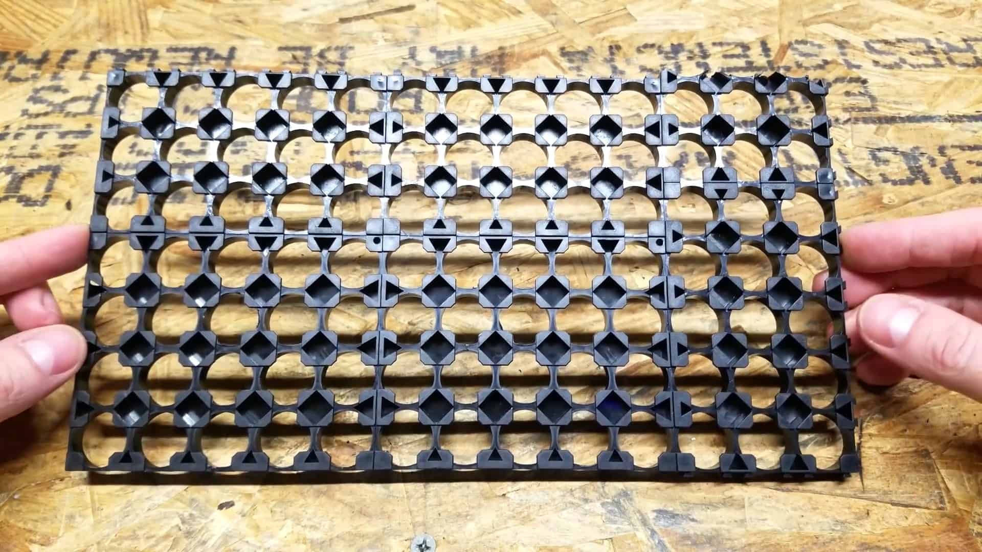
These can often be found in discarded laptops or purchased from electronics recycling centers. Next, you will need 4X5 and 3X5 cell holders to organize and secure the batteries. An ammo can will serve as the container for the battery system.
In order to manage the charging and discharging of the batteries, you will need a 40 Amp BMS or battery management system. This will help ensure that the batteries are properly charged and discharged, and will help prolong their lifespan.
To connect the batteries and the BMS, you will need a spot welder. This tool will allow you to fuse nickel strips to the batteries and connect them to the BMS. You will also need fused nickel strips, heat shrink, and Kapton tape to properly insulate and protect the battery system.
STEP 2 : FIGURING OUT THE CELL CONFIGURATION
To begin building the backup battery system, the first step is to determine how many lithium-ion 18650 batteries can fit inside the chosen ammo can.
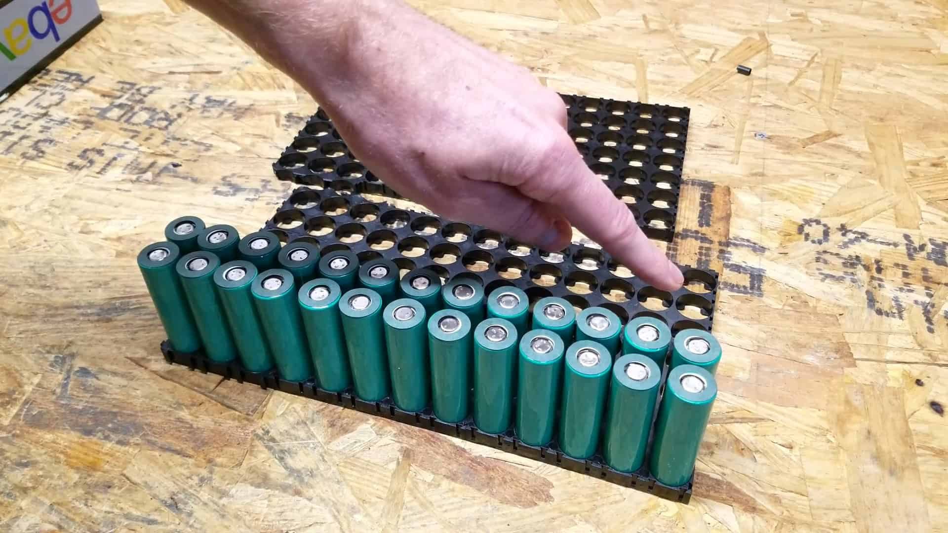
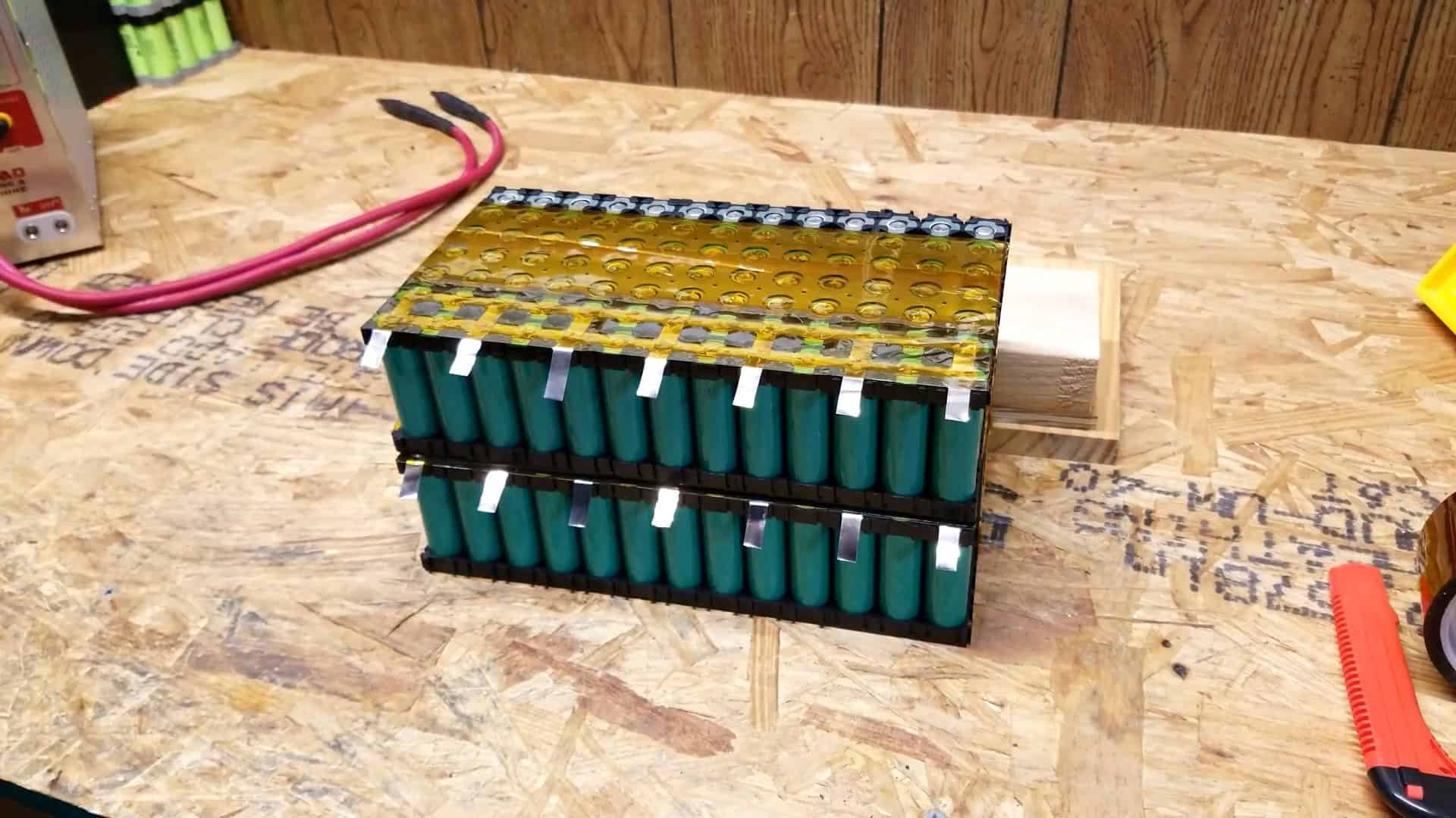
For this project, two packs of 91 18650 cells are used, which equals a total of 182 cells. Next, the 4 X 5 and 3 X 5 cell holders are connected to create two 7 x 13 cell holders.
In order to achieve the desired 24V lithium-ion battery configuration, a 7S combination (7 cells connected in series) is needed. Since a single lithium-ion cell has a nominal voltage of 3.7V, seven groups of 26 cells are connected in series to create a single long 7S battery configuration, which results in a 25V nominal voltage.
This step ensures that the necessary number of batteries are arranged correctly to provide the required voltage for the backup battery system.
STEP 3 : CONNECTING THE CELLS
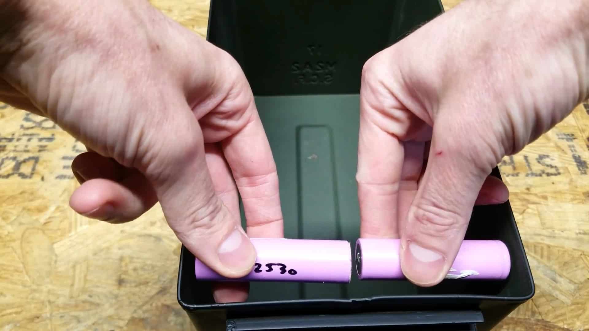
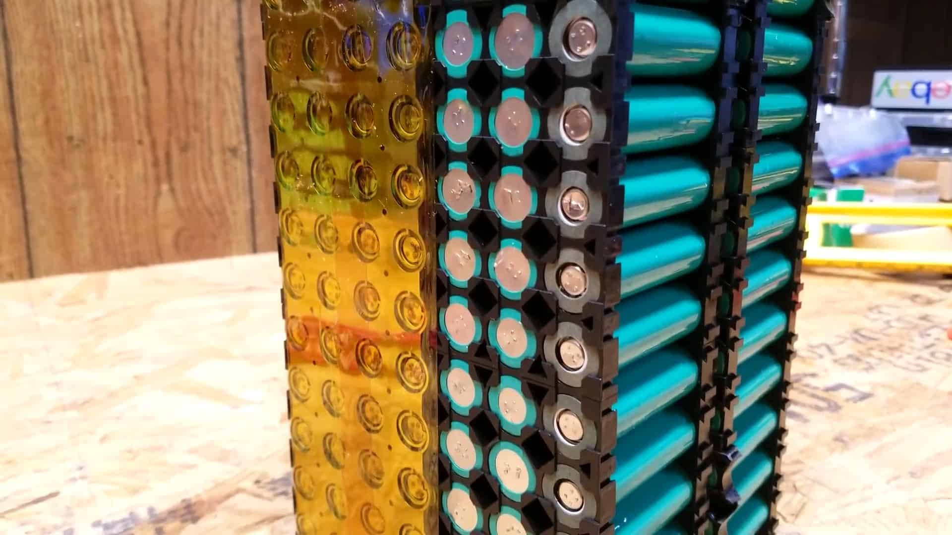
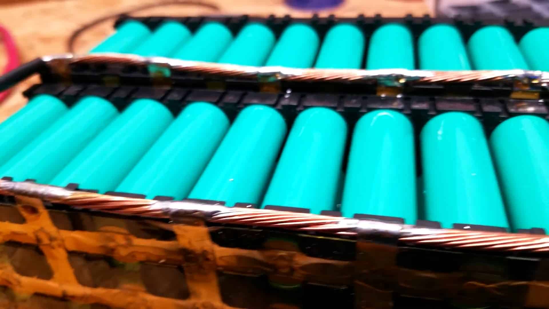
The specific type of lithium-ion cells used in this project are Samsung ICR18650-28A, each with a capacity of 2800mAh.
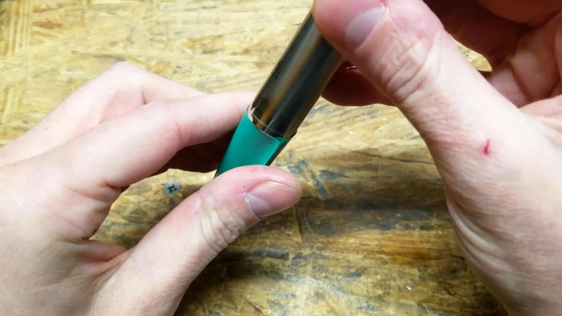
To ensure safety, the cells have been rewrapped with heat shrink and an insulator disk has been added to the positive side of each cell.
During installation, the first 26 cells are connected in parallel with the same polarity, followed by the next 26 cells with opposite polarity, which are then connected in series with the first 26 cells.
The remaining cells are also connected in a similar way, resulting in a 7S 2P configuration, with a maximum capacity of 72.8 amp-hours (26 x 2.8mAh).
STEP 4 : COMPLETING THE SERIES CONNECTION
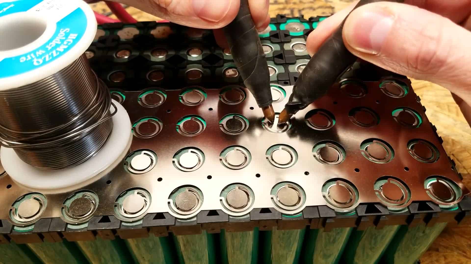
To ensure the safe and reliable connection between the batteries, a four-wide fused nickel strip is used. This strip is carefully placed over the first four cells and then spot welded using a sunkko spot welder.
It is important to note that each individual cell is fused, which means that in case of a short circuit or malfunction, only the affected cell will be disconnected, protecting the rest of the battery pack.
The nickel strip plays a crucial role in connecting the cells in a specific configuration. In this case, the first two rows of cells are connected in parallel, and then the next two rows are connected in series, creating a 7S2P configuration.
By connecting the cells in this way, the battery pack has a maximum capacity of 72.8 amp-hours and a nominal voltage of 25V. This configuration provides a reliable power source for backup power needs.
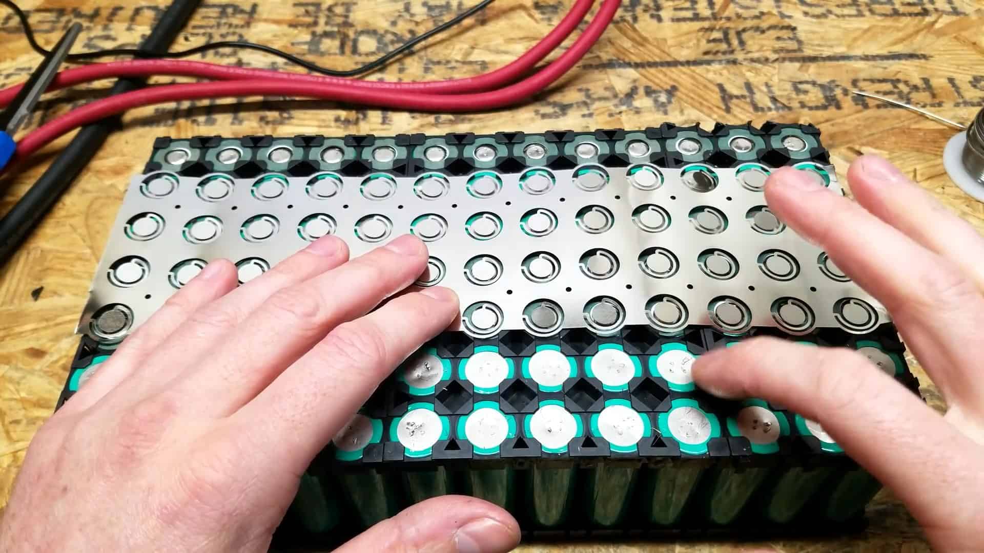
To complete the series connections, the nickel strips are placed and welded on the opposite side of the pack. This is done to ensure that the strip won’t short out the connection by coming in contact with the most negative side of the battery.
The nickel strips are again placed over the first 4 cells and welded in place. Each cell is individually fused for added safety. The nickel strip connects the third and fourth rows in parallel and then connects all rows in series.
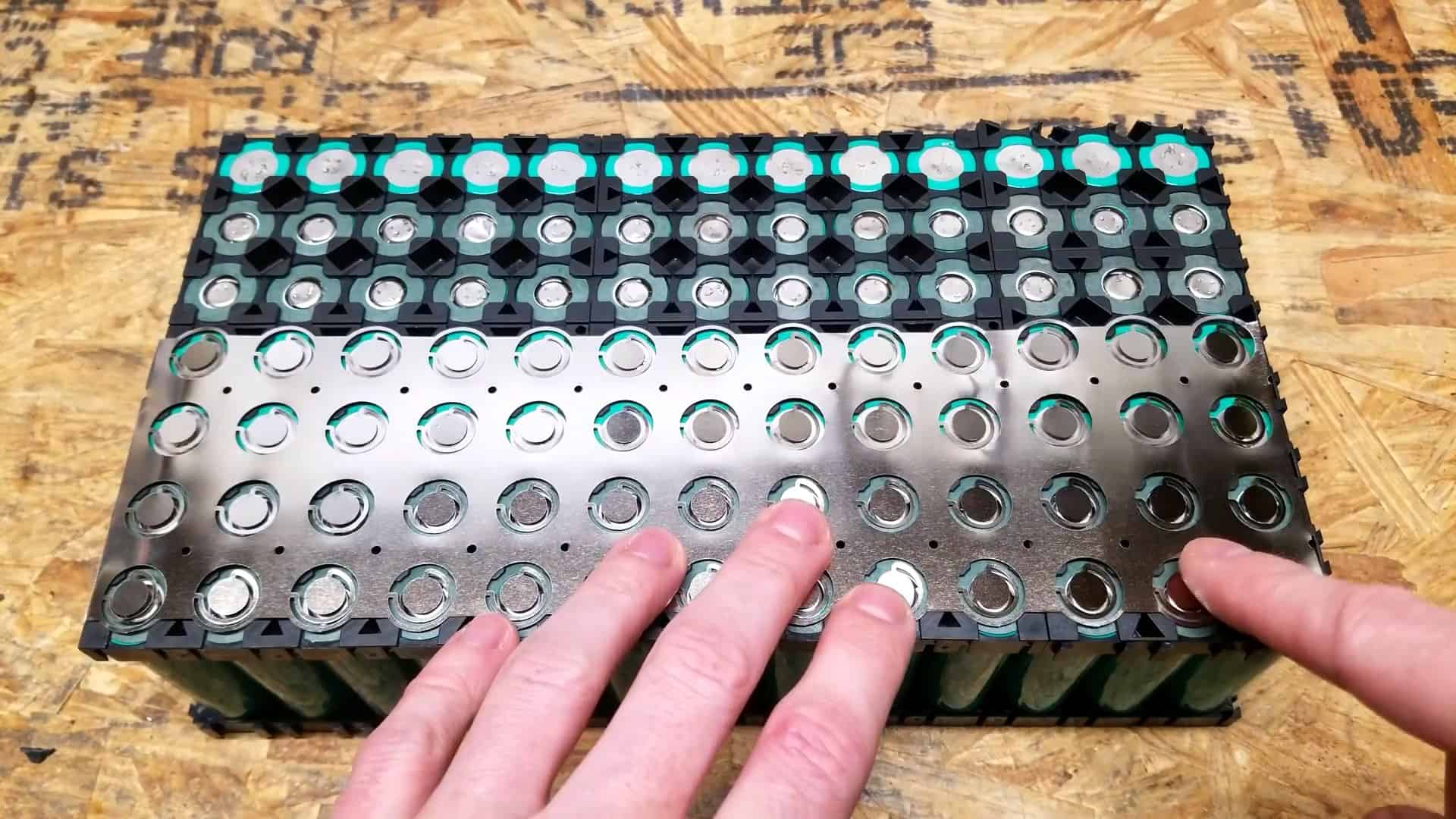
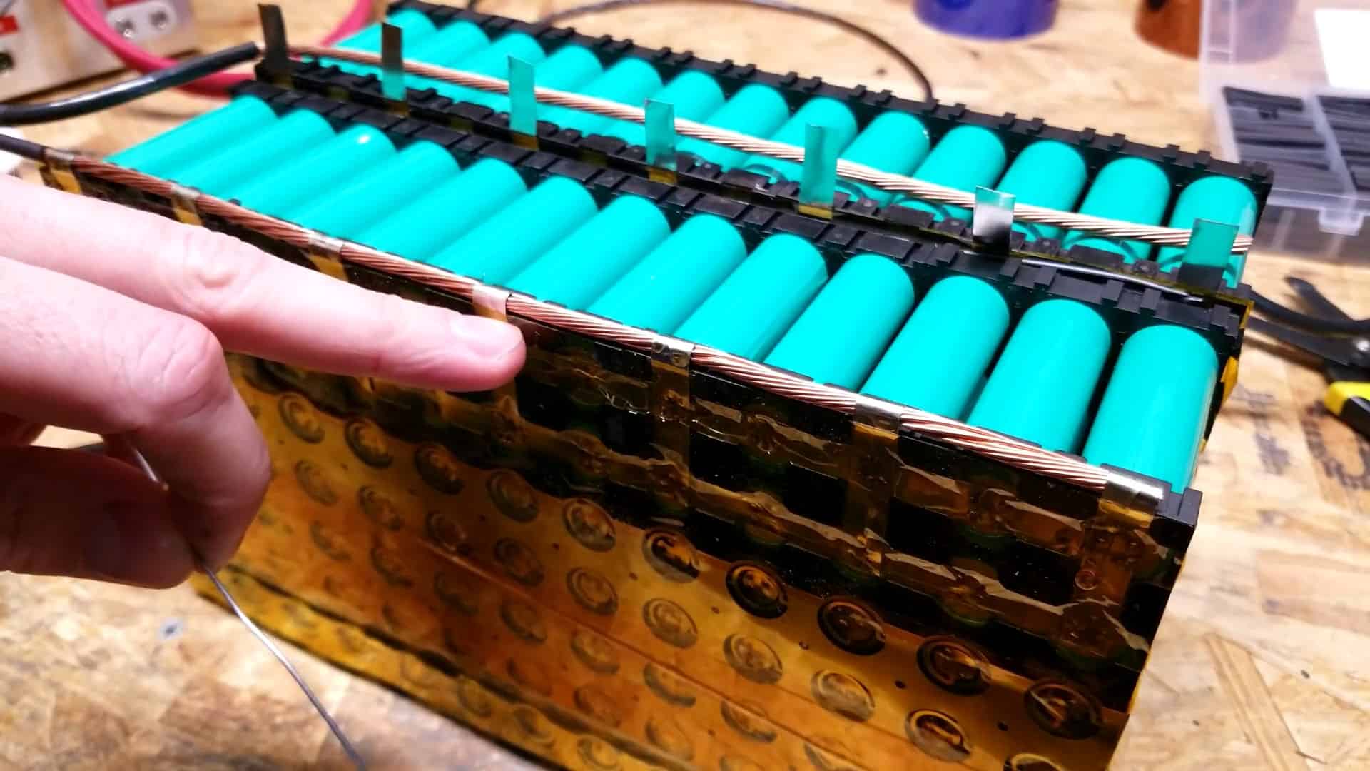
To complete the final connections, 0.15mm standard nickel strips are used to connect the positive ends of the entire battery pack.
The last two rows on the most positive end of the battery are connected using a nickel strip, with smaller pieces of nickel strip placed across these two rows to connect them in parallel.
These smaller pieces are carefully bent so that they can be connected to a separate copper busbar, which will ultimately connect to the positive terminal of the BMS.
STEP 5 : CONNECTING THE OTHER BATTERY PACK
To connect the two separate battery packs, they are first aligned and stacked on top of each other. Then, a fused nickel strip is used to connect the positive end of the first pack to the negative end of the second pack.
Specifically, the nickel strip that connects the first 3 connections on the 1st pack is bent at a 90-degree angle and spot-welded onto the 4th connection on the other pack.
Additionally, the last row of the 4P fused nickel strip is also bent at a 90-degree angle and welded onto the first battery pack.
This connection ensures that the two packs are connected in series, allowing for a total voltage of 25V. Finally, a piece of Kapton tape is placed over the nickel strip to insulate it and hold it together, preventing any unintentional contact between the battery
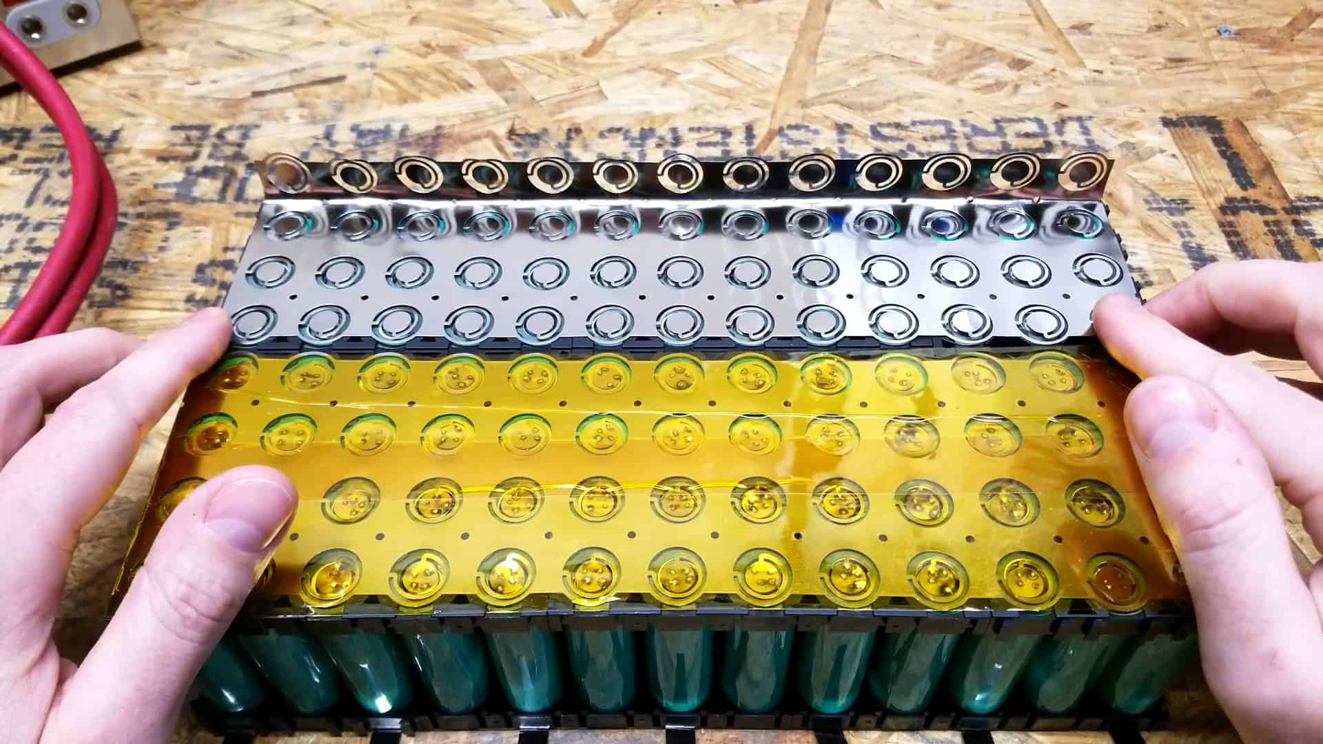
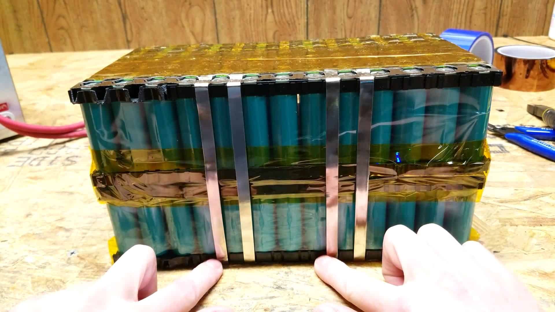
After welding the two packs together, we need to ensure that they are securely held in place. To do this, we use a one-sixteenth-inch ABS plastic sheet that fits perfectly between the two packs. This sheet helps to distribute the pressure and ensures that the packs do not move around.
Once the ABS plastic sheet is in place, the second pack is slowly folded over the top of the first pack. This is done carefully to ensure that the cells are not damaged or shorted. Once the second pack is in place, we need to secure the entire pack together.
We do this by wrapping the entire pack with Kapton tape. The tape helps to insulate the cells and also holds the packs together. It is essential to ensure that the tape is wrapped tightly so that the cells do not move around inside the pack.
To connect the last three unconnected terminals on one side of the battery pack to the single row of unconnected terminals on the other side, four nickel strips are used.
The 4p fused nickel strip is cut so that it can connect the three sides and the other side.
STEP 6 : FINDING THE POSITVE AND NEGATIVE TERMINAL WIRES
To connect the main negative and positive tabs, a THHN copper wire is attached across both terminal ends of the battery pack. The nickel connections are then folded across the wire to hold it in place and soldered.
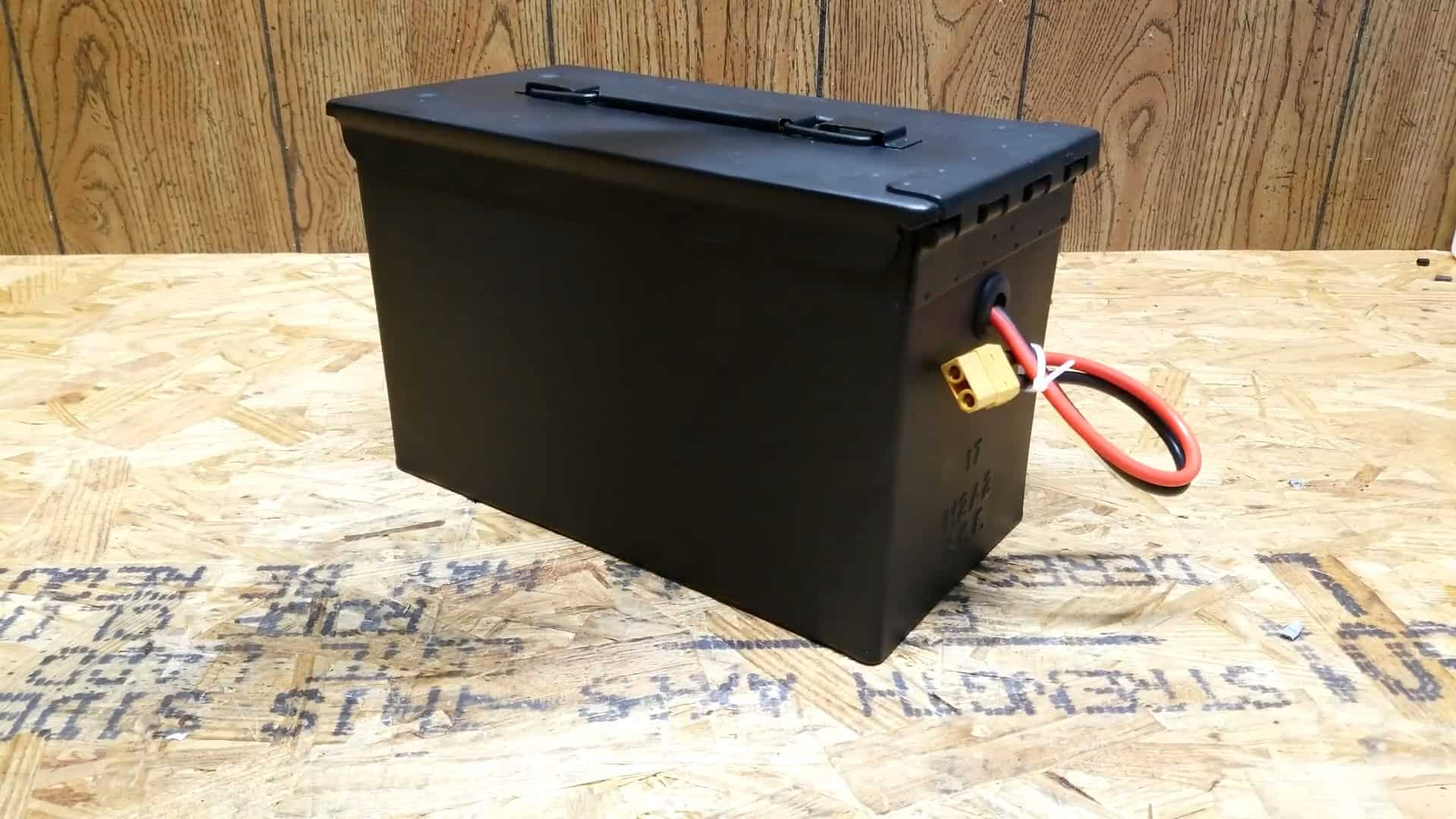
This ensures a secure connection between the battery pack and the external power system. The terminal wires are then connected together with an XT90 connector, which is commonly used in high-power applications due to its ability to handle high current.
STEP 7 : CONNECTING THE BATTERY MANAGEMENT SYSYEM
The next step is to connect the BMS or battery management system to the pack. This is a small circuit board that is used to protect each cell of the battery pack from overcharging and becoming unbalanced and getting damaged. It stops the over-draining when the cells are fully charged.
The BMS used here is a 7S 24V with a charge current of 20A and a discharge current of 40A. It has two negative leads, one connecting the battery and the other for charging and discharging.
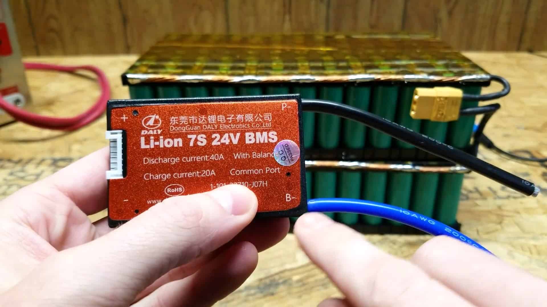
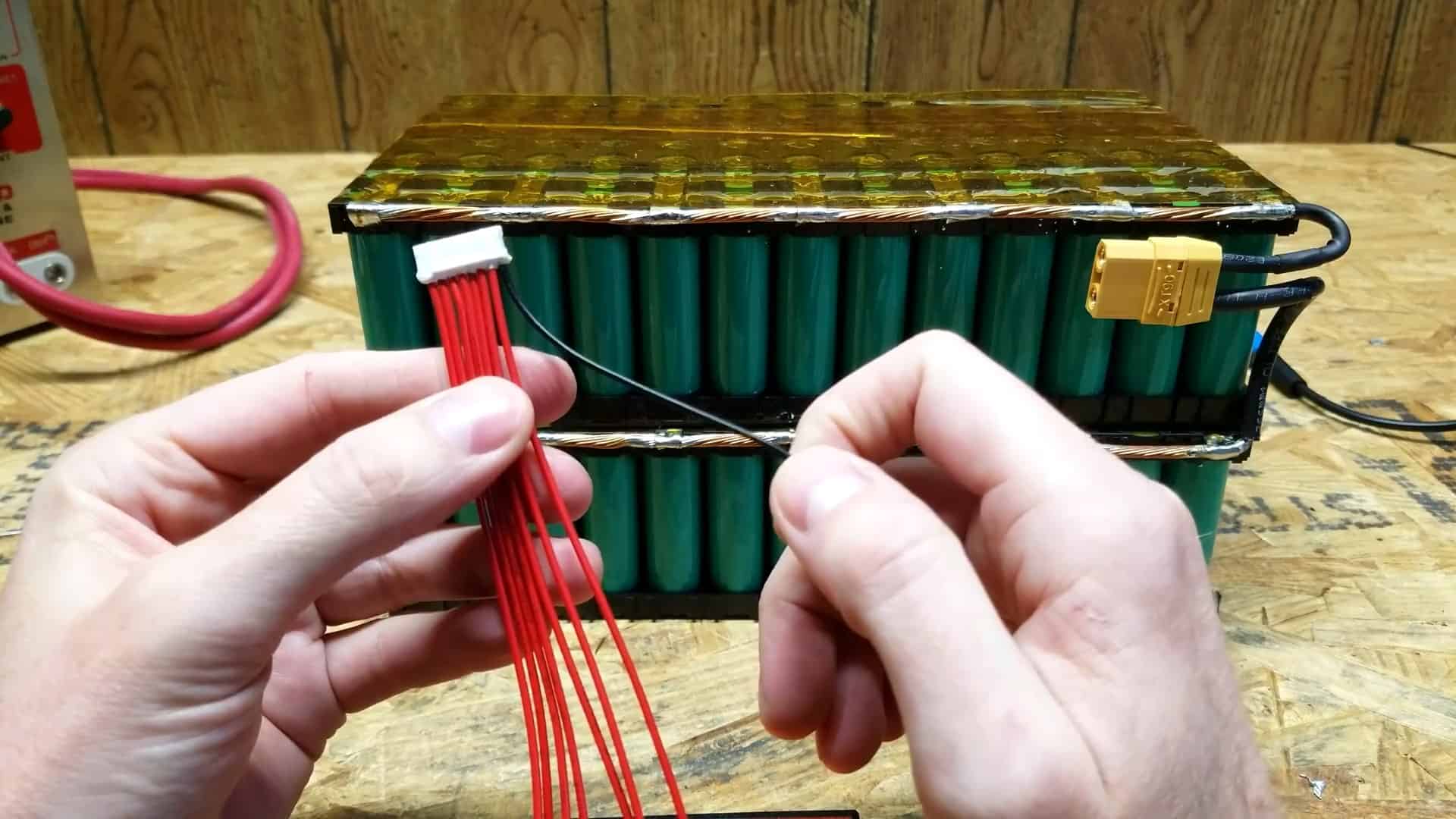
In addition to protecting the battery cells from overcharging and becoming unbalanced, the BMS also has 8 sense or balancing wires that need to be connected to each series of connections on the battery pack.
The black wire is connected to the most negative terminal of the battery pack.
The first red wire is connected to the first series-connected group of cells, the second red wire is connected to the second series-connected group of cells, and so on, until the last red wire is connected to the main positive terminal of the battery pack.
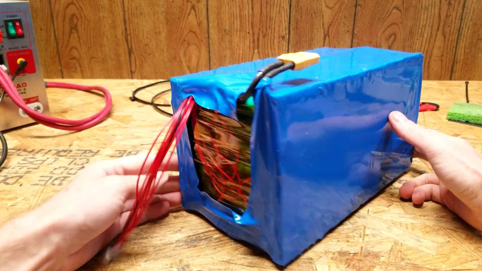
To ensure safety, the entire battery pack is then wrapped in heat shrink.
STEP 8 : INSULATING THE AMMO BOX
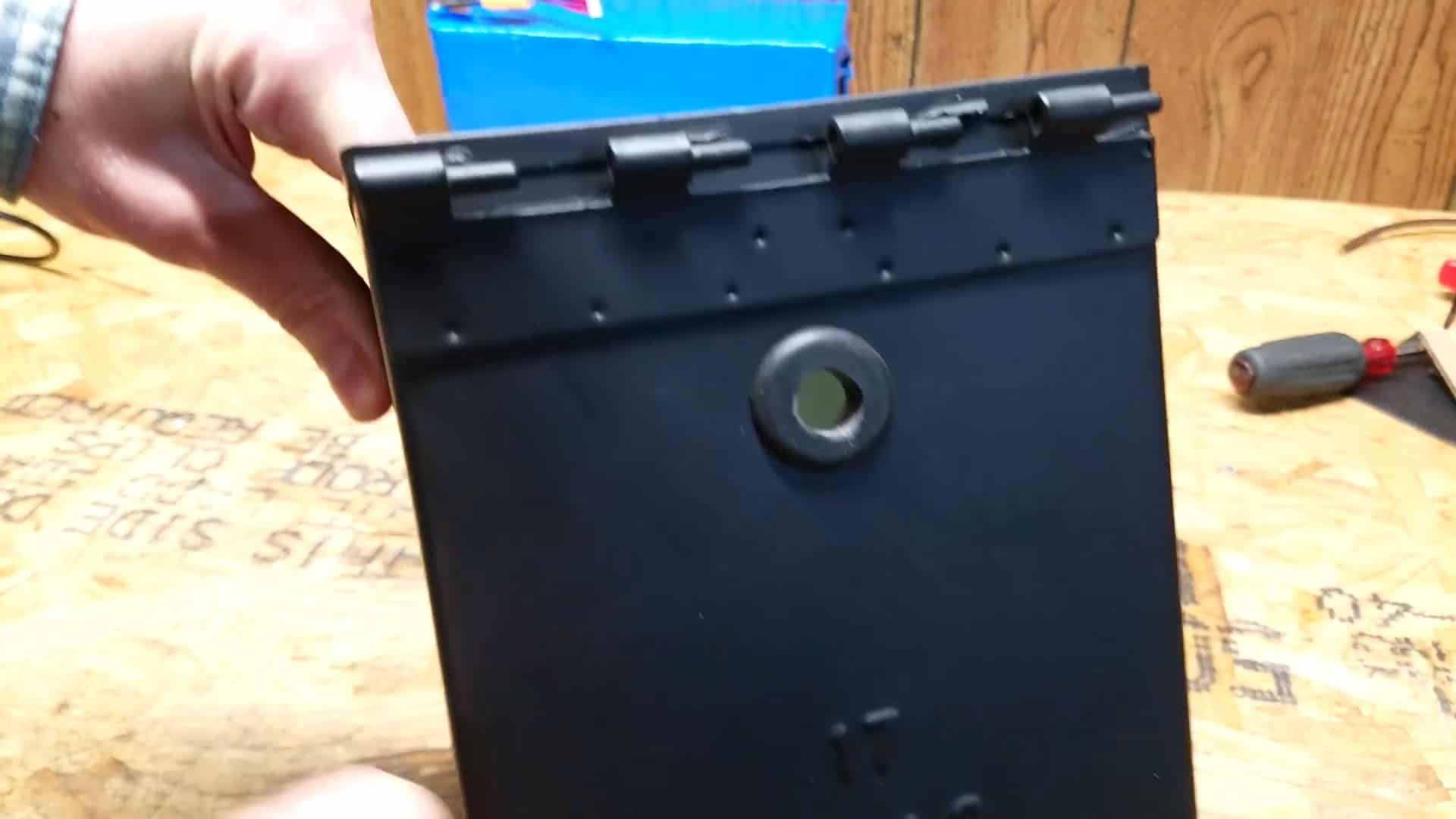
To prepare for the insertion of the battery pack into the ammo box, a hole is drilled at the backside of the box to allow the cables from the battery to pass through.
This ensures that the cables can be connected to the external system. Additionally, a small piece of one-sixteenth-inch ABS plastic is placed at the bottom of the box to provide support and insulation for the battery pack.
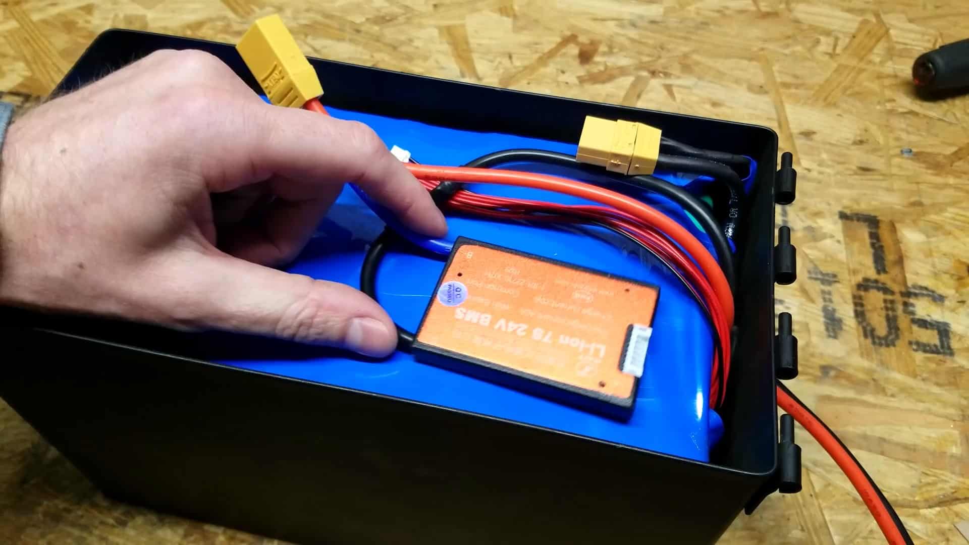
STEP 9 : INSTALLING THE BATTERY
After carefully dropping the battery into the ammo box and placing the BMS on top, the XT90 connector and the balance wires from the battery are connected to the BMS.
The B- terminal on the BMS is then connected to the XT90 connector on the battery. The black wire on the BMS is the charge and discharge lead. To provide extra insulation between the battery pack and the ammo box , we attach two pieces of the insulting ABS sheet on either side of the box.
To provide extra insulation and support for the battery pack inside the ammo box, two pieces of insulating ABS sheet are attached to either side of the box.
This helps to prevent any movement or shifting of the battery pack inside the box, which could potentially damage the connections or components.The lid is put back on the box and the battery build is complete.