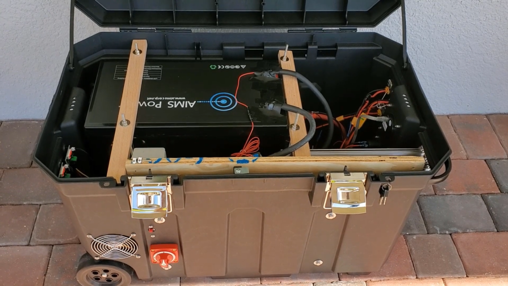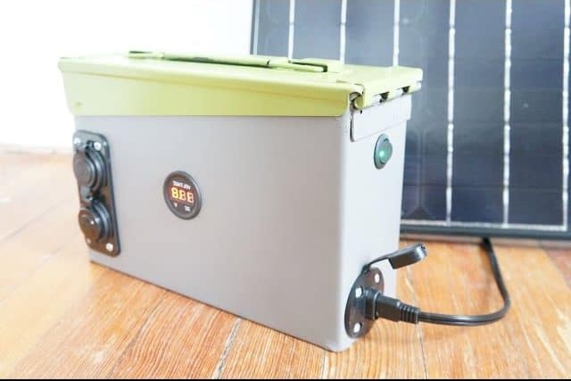
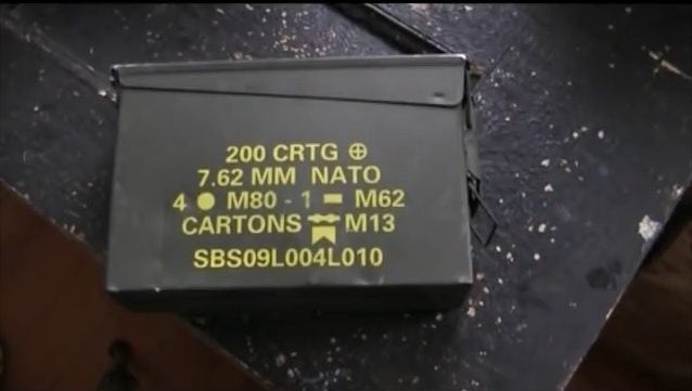
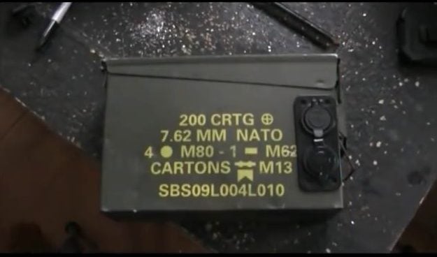
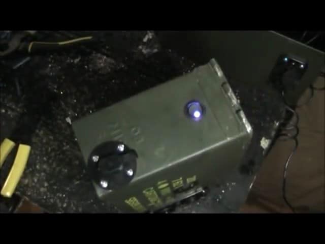
This project goes over the build of a 240W Solar Generator made out of an army box. The box is large enough to hold a 240-watt deep cycle battery.
STEP 1 : THE MATERIALS REQUIRED
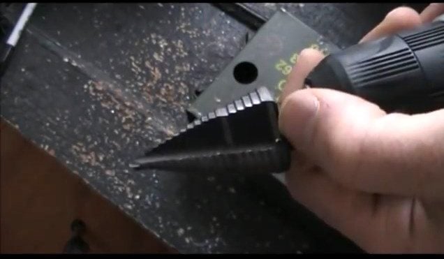
To build the solar generator, you will need a few basic tools. The primary tool required is a drill to make the necessary holes in the metal ammo box.
A step-up drill bit is recommended as it can drill different-sized holes using the same drill bit.
A screwdriver is also necessary, as well as wire cutters and a wire cutting and stripping tool. A crimper is also useful when working with wires.
Pliers can be handy when cutting and manipulating wires, and basic wire cutters are included with most pliers.
To drill the holes in the metal ammo box, you need a step-up drill bit that can drill different-sized holes, using all the same drill bit.
You will need a pair of pliers which might be handy when you are cutting and manipulating wires and then basic wire cutters which also we have on the pliers.
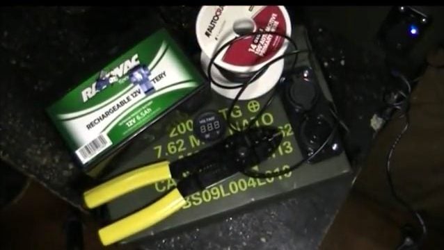
The heart of the solar generator is the battery. A deep cycle battery is required, and it is recommended to use a V max deep cycle battery instead of a Rayovac battery.
Along with the battery, a USB port with a one-amp outlet and a 2.1-amp outlet, and a 12-volt outlet are also necessary.
Terminal connectors, a switch, self-tapping screws, a faceplate, and 14-gauge 17-amp black and red wires are also required.
When connecting the USB and 12V outlets, a 3-prong switch is used, with one of the prongs being gold in color, which serves as the negative terminal.
The switch controls the USB outlet and turns it on and off.
The positive terminal of the USB outlet is connected to the positive terminal on the switch, and the switch is used to break the electrical current when it is turned off.
The second positive terminal on the switch is connected to the positive terminal on the battery.
This creates a flow of electricity from the positive terminal, through the switch, to the positive terminal on the USB port.
The negative terminal on the switch goes to the negative terminal on the battery.
The only purpose of that terminal is to control the LED light on the switch, it needs both positive and negative electrical currents in order to turn that light on.
The negative terminal on the switch is connected to the negative terminal on the battery, and its only purpose is to control the LED light on the switch.
The LED light requires both positive and negative electrical currents to turn on. Similarly, the positive connector on the 12V port is connected to the positive terminal on the battery.
STEP 2 : INSTALLING THE 12V AND USB OUTLET
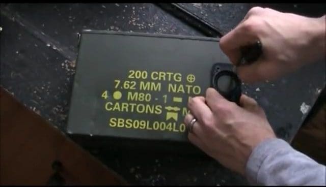
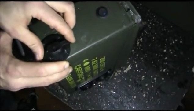
The next step in building the solar generator is to drill holes in the metal ammo box for the 12V and USB outlets using a faceplate as a guide.
To do this, use a marker to trace the inside of the faceplate from both the top and the bottom. This will indicate where the holes need to be drilled.
It is important to find the exact centers when drilling the holes. To ensure this, measure and mark the center points of each hole using a ruler or a measuring tape.
Once the holes have been drilled, insert the 12V and USB outlets into the holes. Each port comes with a little ring that screws on the back, which holds it in place securely.
Make sure to position the ports correctly and tighten the screws on the rings to ensure that they are securely fastened in place.
This will prevent any movement or dislodging of the ports when in use.
STEP 3 : POWER SWITCH AND POWER SOCKET
The next step is to install the power switch, SAE Solar Power Socket, and voltmeter.
The power switch controls the flow of electricity and turns on/off the USB outlet, while the SAE socket allows the generator to be charged using a solar panel.
STEP 4 : WORKING WITH THE BATTERIES
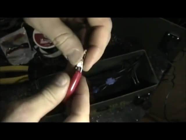
To begin wiring the battery, you will need a few tools and materials, including the battery itself, quick disconnects, squeeze connectors, wire cutters, a stripping tool, and black and red wires.
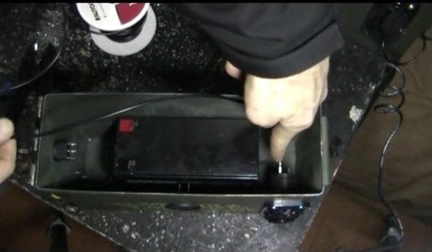
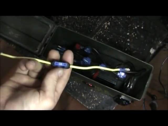
Once you have everything you need, place the battery into the ammo box along with the ports, switch, and voltmeter.
Place the max battery into the ammo box. So we’ve got everything in place, we have our ports in place, we have our battery in place, we’ve got our switch in place, and our voltmeter. We’re gonna start by wiring the USB port.
STEP 5 : CONNECTING THE USB PORT ,LED AND THE SAE PORT
Start by wiring the USB port, connecting the positive terminal to the positive terminal on the switch, which is then connected to the positive terminal on the battery.
The negative terminal on the USB port is connected directly to the negative terminal on the battery.
This switch will break the flow of electricity on the positive side and that’s what’s going to turn our USB port on and off.
To properly wire the tabs batteries, you will need several tools and materials such as quick disconnects, squeeze connectors, wire cutters and strippers, and black and red wires.
Begin by placing the V max battery into the ammo box and securing it in place.
Now, it’s time to wire the USB port. First, use squeeze connectors to connect the USB port’s negative terminal to the same negative terminal as the 12-volt port.

Next, connect the positive terminal from the switch to the positive wire coming from the 12-volt port, and then continue that positive flow from the switch to the positive terminal on the battery, all through quick disconnects.
This creates a complete circuit for the USB port and 12-volt outlet to be connected to the battery through the power switch.
So we now have our USB port and our 12-volt outlet connected to the battery through the power switch.
We’ve got the negative terminal of the USB port, going to the negative terminal on the battery, we have the positive terminal of the USB port.
Then we’ve got a positive going from the switch to the positive on the battery all through quick disconnects.
The negative terminal on the battery connects to the negative terminal on the switch, which enables the switch’s LED light to turn on without any negative current flow.
To power the LED light, connect it to the negative terminal on the battery.
Next, connect the negative of the voltmeter directly to the battery and use insulated clamps to connect the positive wire to the switch for the USB port.
Then, connect the positive wire leading to the positive terminal on the switch so that the voltmeter turns on and off with the switch button.
To ensure the battery can be charged, cover the SAE port and connect it using squeeze connectors to the positive and negative terminals of the battery.
STEP 6 : ADDING THE FUSE
To ensure that the generator is protected from overloading and potential damage, it is essential to install a 15amp fuse. This fuse acts as a barrier between the battery and the internal wiring of the generator.
In the event that the current flowing through the wiring is too high, the fuse will break and stop all electrical current from reaching the battery. It serves as a safeguard against any potential overheating or overload issues that may arise within the wiring.
It is critical to ensure that the fuse is properly installed and connected to the positive terminal of the battery. This will enable it to provide the necessary protection for the generator.
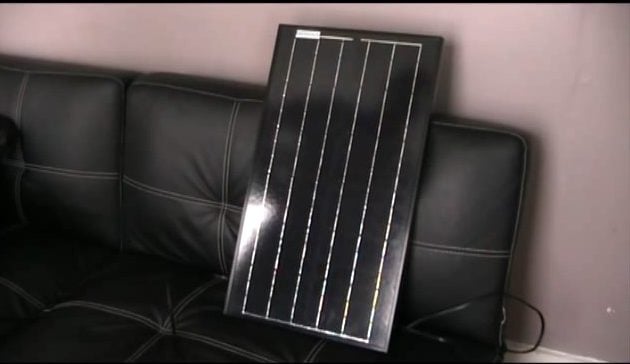
STEP 7 : CONNECTING SOLAR PANEL AND CHARGE CONTROLLLER TO THE GENERATOR
The next step is connecting a solar panel to your generator. To begin, connect the wires coming out of the solar panel into the charge controller.
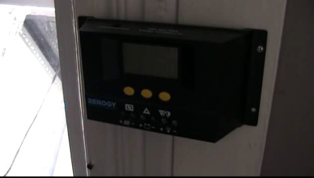
It is important to note that the charge controller is responsible for preventing the battery from overcharging, which can damage the battery.
Therefore, it is important to ensure that the voltage from the solar panel does not exceed 15 volts.
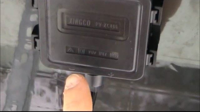
Next, connect the SAE cord from the generator to the charge controller. This will allow the generator to receive power from the solar panel, providing a sustainable source of energy.

Once all the connections are in place, simply place the panel on the charge controller, connect the charge controller to the generator, and you’re done.
Image Credits : Reconstruct Your Life