As a survivalist, being self-sufficient and prepared for unexpected emergencies is paramount. In the event of a power outage or natural disaster, access to electricity can mean the difference between life and death.
That’s where a DIY pedal-powered generator comes in. By repurposing an old car alternator and a bicycle, you can create a reliable and sustainable source of power to charge your devices and keep your essential appliances running.
STEP 1 : MATERIALS REQUIRED
The materials you need to build this generator include a bike, MDF (medium-density fiberboard) for the base plinth, a magnetic trainer stand for the bike, an alternator, a drive belt, a 12V battery, cable connectors, a 12V socket, a multimeter, a screwdriver, and insulation tape.
The bike serves as the primary power source for the generator, while the MDF provides a sturdy base for the generator to sit on.
The magnetic trainer stand is essential as it provides a way to secure the bike in place while it powers the generator. The alternator is responsible for converting the mechanical energy produced by pedaling the bike into electrical energy, which is stored in the 12V battery.
To connect the components, cable connectors are necessary, while a 12V socket allows you to connect your devices and gadgets to the generator.
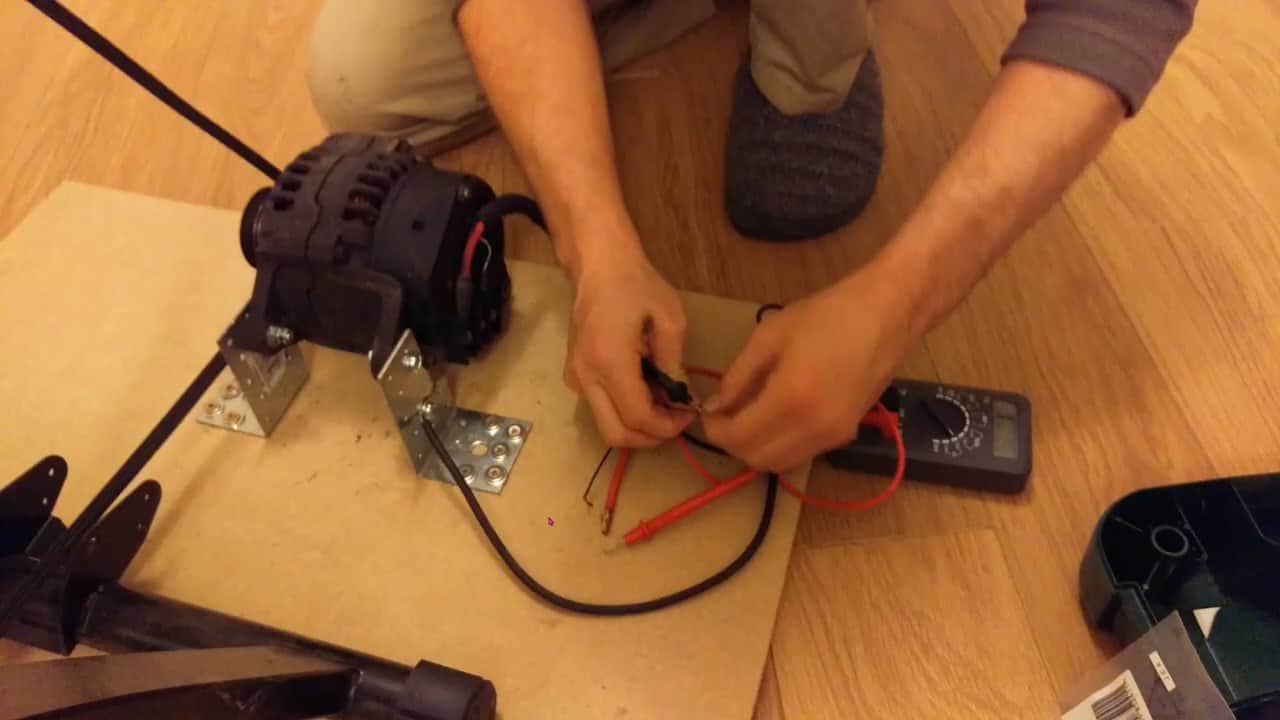
A multimeter is used to measure the voltage and ensure the generator is functioning correctly.

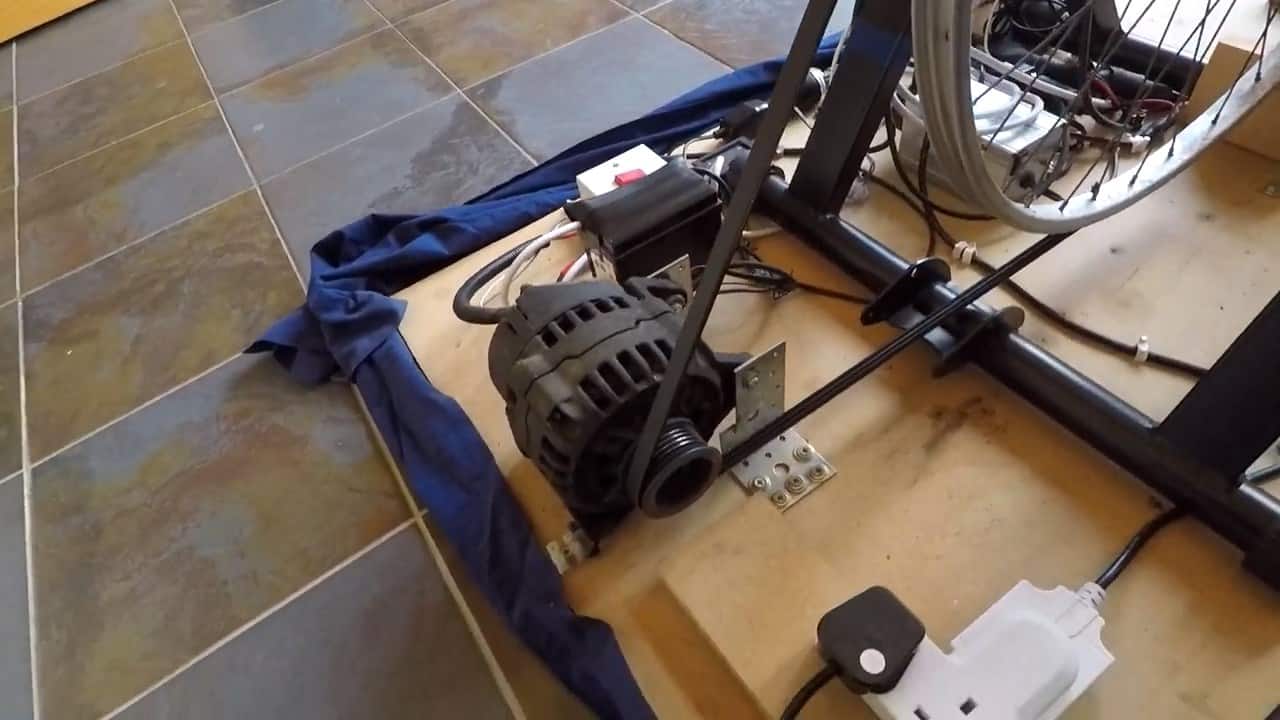
STEP 2 : MOUNTING THE BIKE AND THE ALTERNATOR TO A BOARD
To provide a stable foundation for the generator, begin by mounting the rear end of the bike and all the other components onto a sturdy one-inch thick MDF board.
This board provides ample stability and prevents any unnecessary movement during use. In order to accommodate the bike’s rear wheel being placed in a stand, it’s necessary to add an extension to the front of the board.
This extension bit compensates for the height difference and ensures that the generator remains level and balanced.
The alternator is a crucial component of this DIY pedal-powered generator, as it is responsible for generating electricity from the mechanical energy produced by pedaling the bike.
Therefore, it is crucial to ensure that it is securely mounted onto the base to prevent any potential accidents or malfunctions.
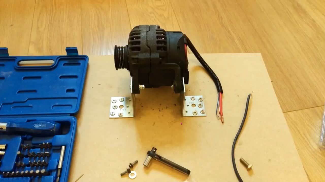
To mount the alternator onto the base, brackets are used to provide a secure and stable attachment. The bolts connect the alternator to the brackets, and the brackets are then screwed down onto the base.
It is important to ensure that the alternator is bolted down tightly to prevent any movement during operation. As the generator produces electricity, there is a considerable amount of force that pulls the alternator forwards, so it needs to be securely bolted down to prevent any damage to the alternator or other components.
STEP 3 : ALIGNING THE BIKE AND THE ALTERNATOR PULLEY
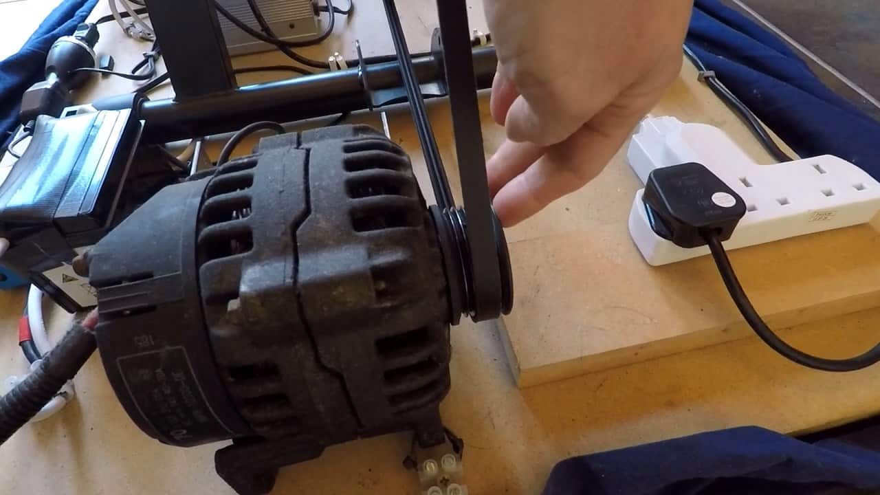
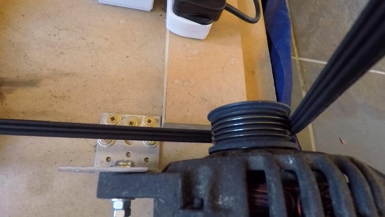
Alignment is crucial in building a functional pedal-powered generator. To ensure proper alignment, make sure that the wheel of the bike is in line with the alternator pulley.
It is also important to note that different bike wheels have a rim bed and rim walls. To determine the correct drive belt size, measure the internal width of the rim bed.
It is recommended to use a drive belt that fits purely in the rim bed to avoid slipping during pedaling. This will ensure maximum power output and prevent damage to the drive belt or the bike wheel.

It’s essential to ensure that the bike wheel and the alternator pulley are aligned correctly. This is important because if they’re not aligned correctly, the drive belt won’t fit properly and may slip off, causing the generator to stop working.
Therefore, take the time to measure and adjust the alignment before moving on to the next step.
When selecting a drive belt, keep in mind that the belt should fit the internal width of the rim bed and the width and depth of the alternator pulley grooves.
It’s important to get a belt that fits correctly, as a loose or tight belt can cause damage to the alternator and reduce the generator’s efficiency.
Additionally, it’s crucial to ensure that the belt is long enough to wrap around the bike wheel and the alternator pulley. A typical drive belt used in a car won’t be long enough because it’s only designed to go around the pulley on the engine.
A belt that is too short can cause unnecessary strain on the alternator and the bike’s rear wheel, which may result in wear and tear or breakage over time. Therefore, it’s essential to choose the right length of belt to avoid any potential damage and ensure the generator works smoothly.
STEP 4 : CONFIGURING THE ALTERNATOR
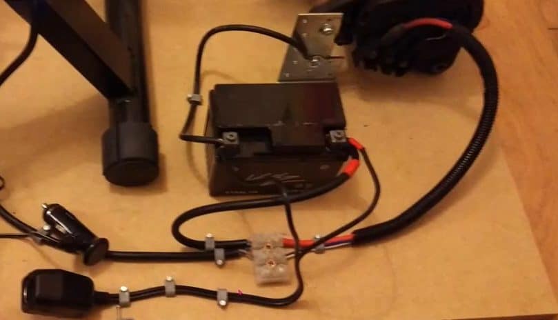
The car alternator used in this project has three wires that come out of it. One is a thick output wire, which supplies the main power to the devices.
The other two are smaller cables, one for voltage sensing and the other for field coil ignition.
The voltage sensing wire goes directly to the 12V lead-acid battery used in this project. The field coil ignition wire, on the other hand, is responsible for generating power in the alternator.
This is because an alternator doesn’t have any permanent magnets in it. To get it to generate power, you need to apply a small voltage through the field coil.
To understand how the generator works, it is important to know that any device that generates electricity works by either moving electrical charges through a stationary magnetic field or by moving a magnetic field around a charge.
In the case of the car alternator used in this project, there are three wires attached to it. One wire is the main power output wire, which supplies power to the devices connected to it.
The other two wires are the voltage sensing wire and the field coil ignition wire.
The voltage sensing wire is connected directly to the 12V lead-acid battery. The alternator needs a small voltage applied to the field coil ignition wire to generate a magnetic field, as it doesn’t have any permanent magnets inside it.
When the voltage is applied, the magnetic field is generated, which allows the alternator to generate power when the shaft is turned via the drive belt.
Once the alternator starts generating its own power, you don’t need to keep applying voltage to the field coil.
To complete the circuit and allow the alternator to charge the battery, the negative output from the alternator should be connected to the negative terminal of the battery, while the positive output from the alternator should be connected to the positive terminal of the battery.
This ensures that the current flows from the alternator to the battery, charging it up.
The third wire coming from the alternator is the field coil activator wire. It is connected to a switch, which allows you to turn the field coil on and off. When the switch is closed, the circuit is completed, and the field coil is activated, generating a magnetic field.
This magnetic field, in turn, induces an electrical current in the alternator, allowing it to generate power.
STEP 5 : CONNECTING THE BATTERY
A standard 12V cigarette lighter socket is then connected to the terminals of the lead-acid battery. When power is needed, the socket draws power from the battery.
As soon as the pedal-powered generator starts to produce electricity, it switches to drawing power from the alternator, which simultaneously powers any device or gadget connected to the socket while recharging the battery.
This ensures a continuous and reliable power source, providing you with electricity for as long as you keep pedaling.

It is important to note that the alternator used in this DIY pedal-powered generator has a specific voltage tolerance range of 11 to 14V.
Therefore, it is necessary to use appropriate devices that are compatible with this range. To allow for charging of multiple devices simultaneously, a modular splitter is connected to the cigarette lighter power socket.
However, it is crucial to ensure that the plug comes with a fuse or that the devices being charged are rated to the appropriate power for safe and efficient charging.

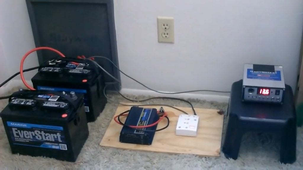
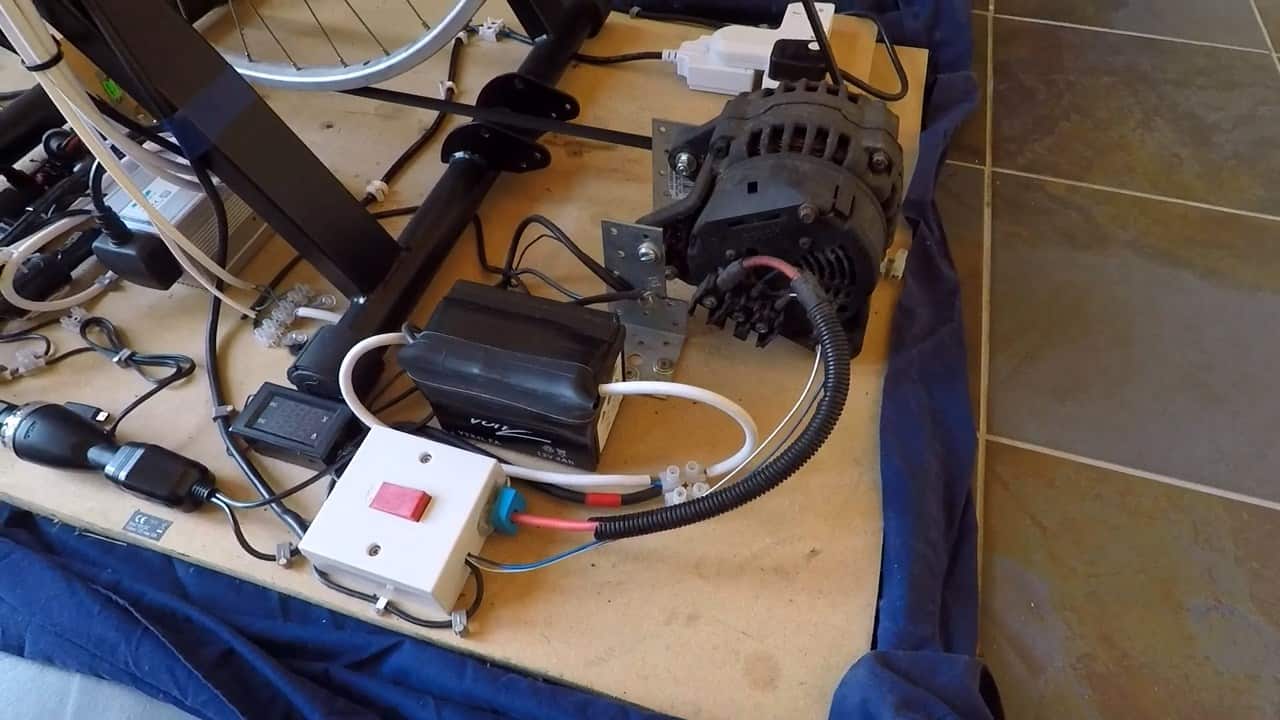
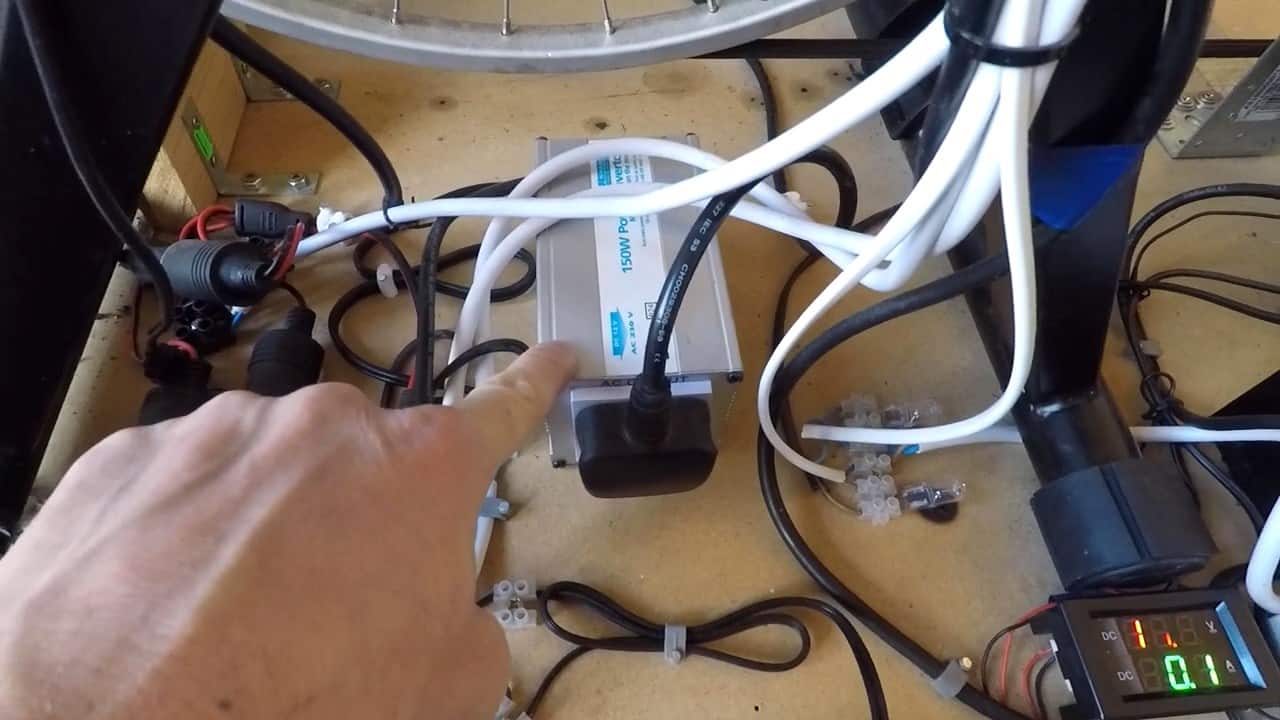
STEP 6 : ADDING A POWER INVERTOR AND A MASTER SWITCH
If you plan to power devices that require alternating current, you will need a power inverter to convert the direct current (DC) output from the alternator to alternating current (AC).
In this setup, a 150W power inverter is connected to the circuit. The alternator actually generates alternating current, but it has a rectification circuit built into it, which changes it to DC.
The inverter then takes this DC output and converts it back to AC, which can power devices that require AC, such as small household appliances, electronic devices, and power tools.
To complete the setup, we need to add a master switch that controls the flow of electricity in the circuit. This switch is essential for controlling the system and isolating the battery and alternator from the circuit when necessary.
The master switch is connected to the battery and is used to turn it on or off. When the switch is turned off, it stops any drain from the battery through the field coil, saving the battery’s charge.
The switch also connects the multi sockets that charge various devices. By turning on the switch, the circuit is complete, and electricity flows from the battery to the inverter and through the alternator, generating power to charge devices.
The master switch can also be used to isolate the battery and alternator from the circuit when necessary. For example, when performing maintenance on the system or transporting it, the switch can be turned off, disconnecting the battery and preventing any accidental discharge.
In addition, the switch isolates the remote switch and the battery from the field coil completely. This ensures that the field coil is only activated when the switch is turned on and prevents any accidental activation.
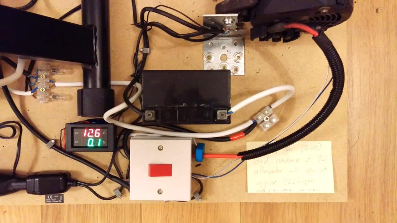
It is important to note that AC generating devices such as alternators have a minimum speed of operation for stability. It is recommended to check the manufacturer’s guidelines to determine the minimum speed for your specific alternator.
If the alternator is operated below this recommended speed, it can result in a periodically varying force that acts as a resistance to your pedaling.
This can make it more difficult to pedal and reduce the overall efficiency of the system. Therefore, it is crucial to ensure that the alternator is operated within its recommended speed range to achieve optimal performance.
Image Credits : Systemic Creative