The prospect of a power generator that is completely silent, has the capability to run large power loads, and does not rely on gasoline is a truly remarkable idea.
In this project, we will explore the step-by-step process of building a large 2000W Portable Solar Generator that can effortlessly power a variety of appliances – from charging your phone to running a table saw.
With this solar power generator, you will no longer have to worry about the noise, fumes, and hassle associated with traditional gasoline-powered generators.
Instead, you will be able to enjoy a clean, reliable, and silent source of power that utilizes the sun’s energy to generate electricity.
Our build will involve carefully selecting a durable and waterproof box to house the various components, including a powerful 12V Optima deep cycle battery, a 2000W inverter from Krieger with an active fan for ventilation and remote control switch, and a 100W Solar Panel from Renogy with a 30A Solar Charge Controller.
Additionally, we will incorporate a 1.5A Battery Maintainer/Float or Trickle Charger to enable charging with standard AC power, ensuring that the generator is always ready for use.
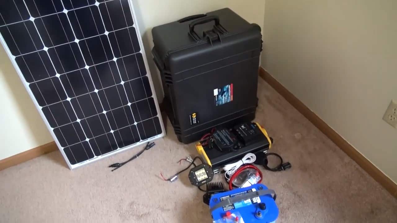
STEP 1 : SELECTING A BOX
When embarking on the process of building a large 2000W Portable Solar Generator, it is crucial to select a durable and spacious box that can safely hold all of the necessary components.
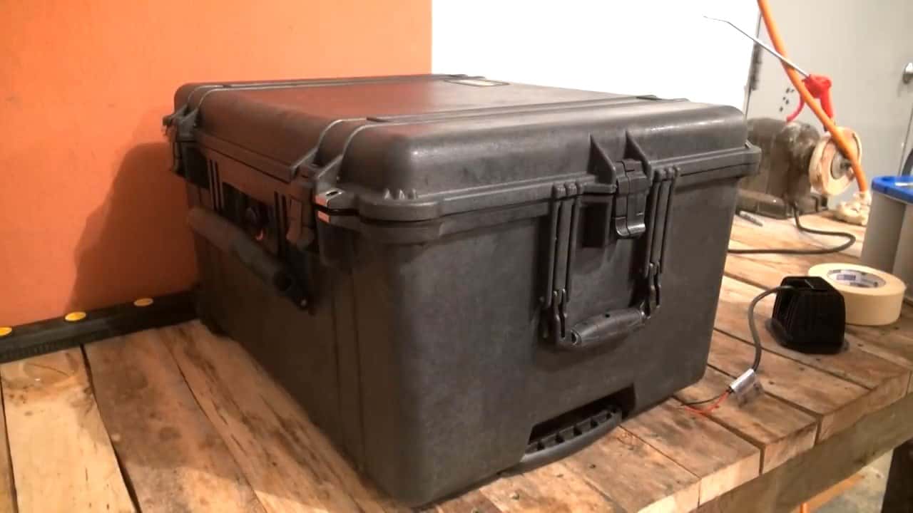
For our project, we have chosen the Pelican 1620 Protector Case – a high-quality case that boasts dustproof, waterproof, and durable features.
One of the standout features of the Pelican 1620 Protector Case is its spacious interior, which offers ample room for all of the components needed for our solar generator.
In addition to its impressive size, this case is also equipped with wheels on the bottom, making it easy to move around as needed.
Its heavy-duty handles on either side further enhance its portability and convenience.
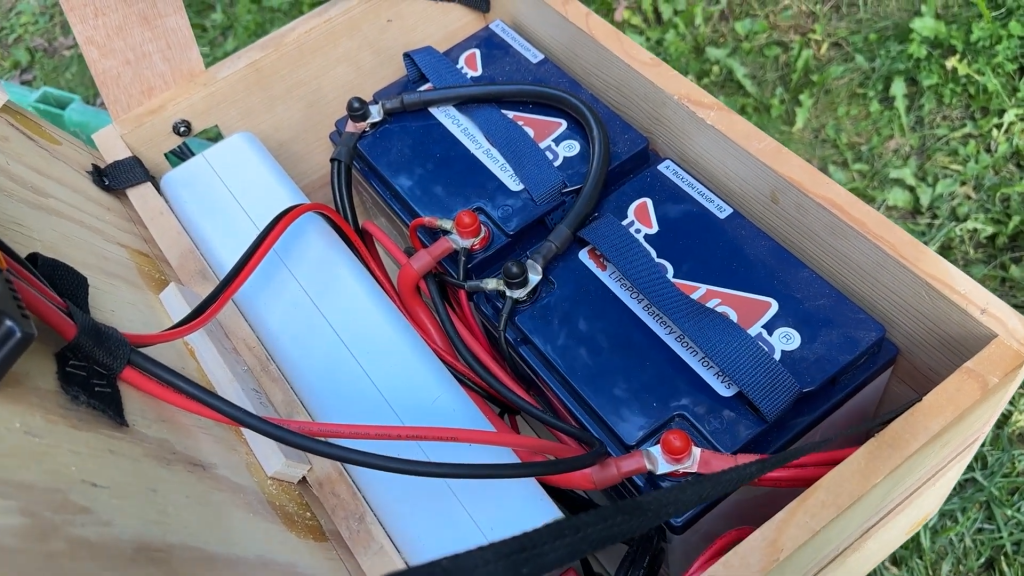
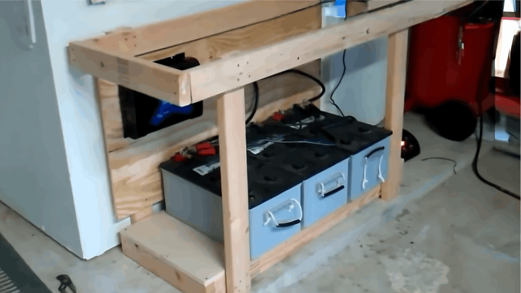
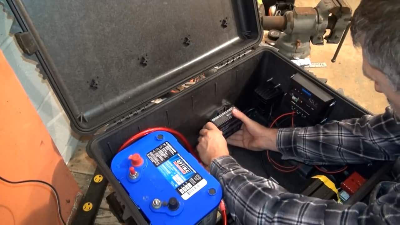
STEP 2 : ADDING A DEEP CYCLE BATTERY
When it comes to building a large 2000W Portable Solar Generator, selecting a reliable battery is essential for powering your appliances efficiently and safely.
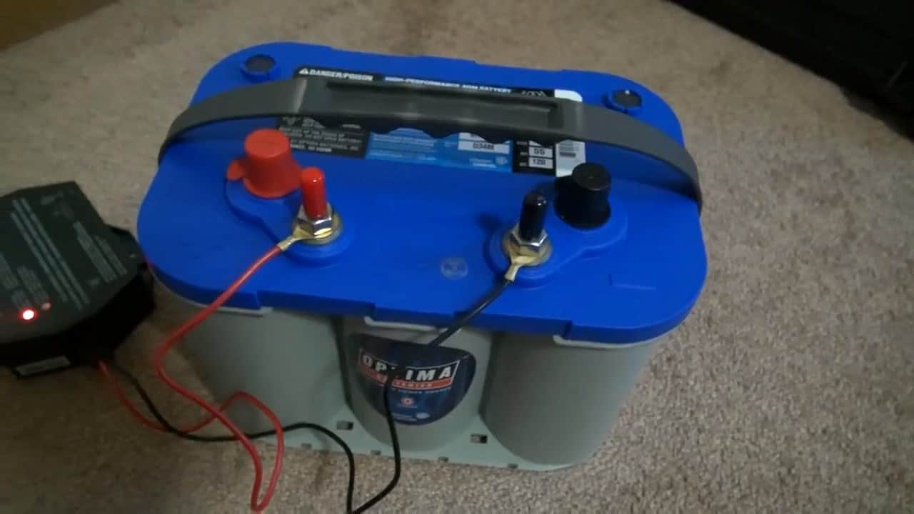
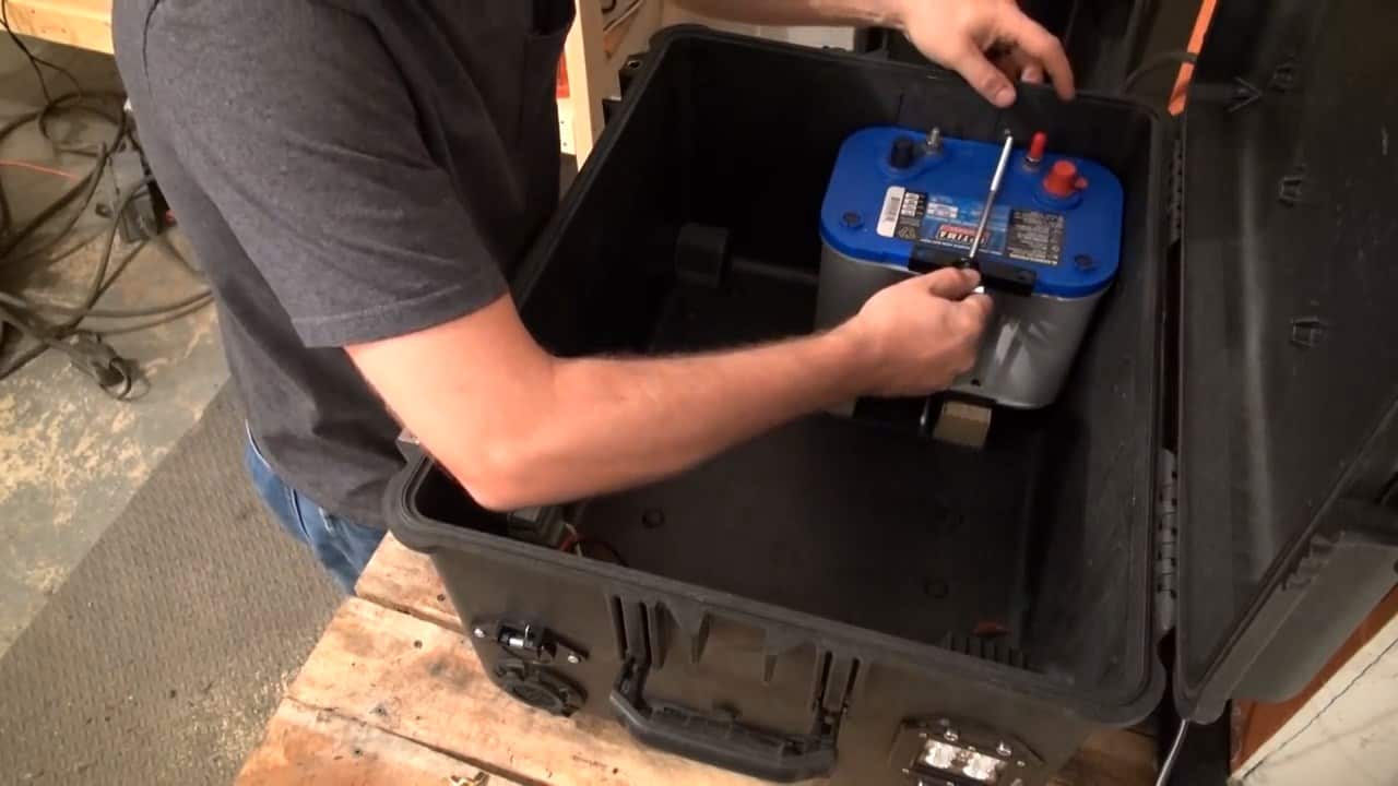
In our project, we have chosen the AGM glass mat, coil wound style, 12V Optima deep cycle battery for its exceptional performance and durability.
One of the main advantages of a deep cycle battery is its ability to discharge to a greater extent without reducing its lifespan.
This means that you can use your generator for longer periods of time without worrying about damaging your battery.
The Optima battery, in particular, is known for its reliable performance and ability to withstand tough environmental conditions.
Furthermore, the Optima battery’s versatile design allows it to be mounted in any orientation, whether it be on its side, back, or even upside down.
This provides you with greater flexibility in how you choose to set up your solar generator.
STEP 3 : INVERTER AND THE SOLAR PANELS
After selecting a reliable battery, the next important component for building a large 2000W Portable Solar Generator is an efficient inverter.
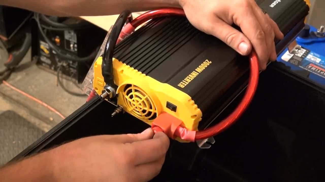
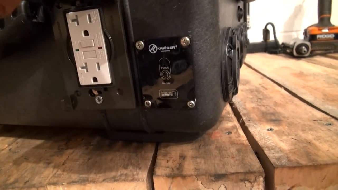
For our project, we have chosen the 2000W inverter from Krieger, which is known for its high-quality performance and durability.
One of the key features of this inverter is its large terminals on the back, which make wiring easy and convenient. This helps to simplify the installation process, allowing you to set up your solar generator quickly and efficiently.
Additionally, the inverter is equipped with an active fan for ventilation, which helps to prevent overheating.
Another great feature of the Krieger inverter is its remote control switch, which allows you to turn your generator on and off from a distance.
This provides added convenience and ease of use, particularly when you’re using your generator in remote locations or hard-to-reach areas.
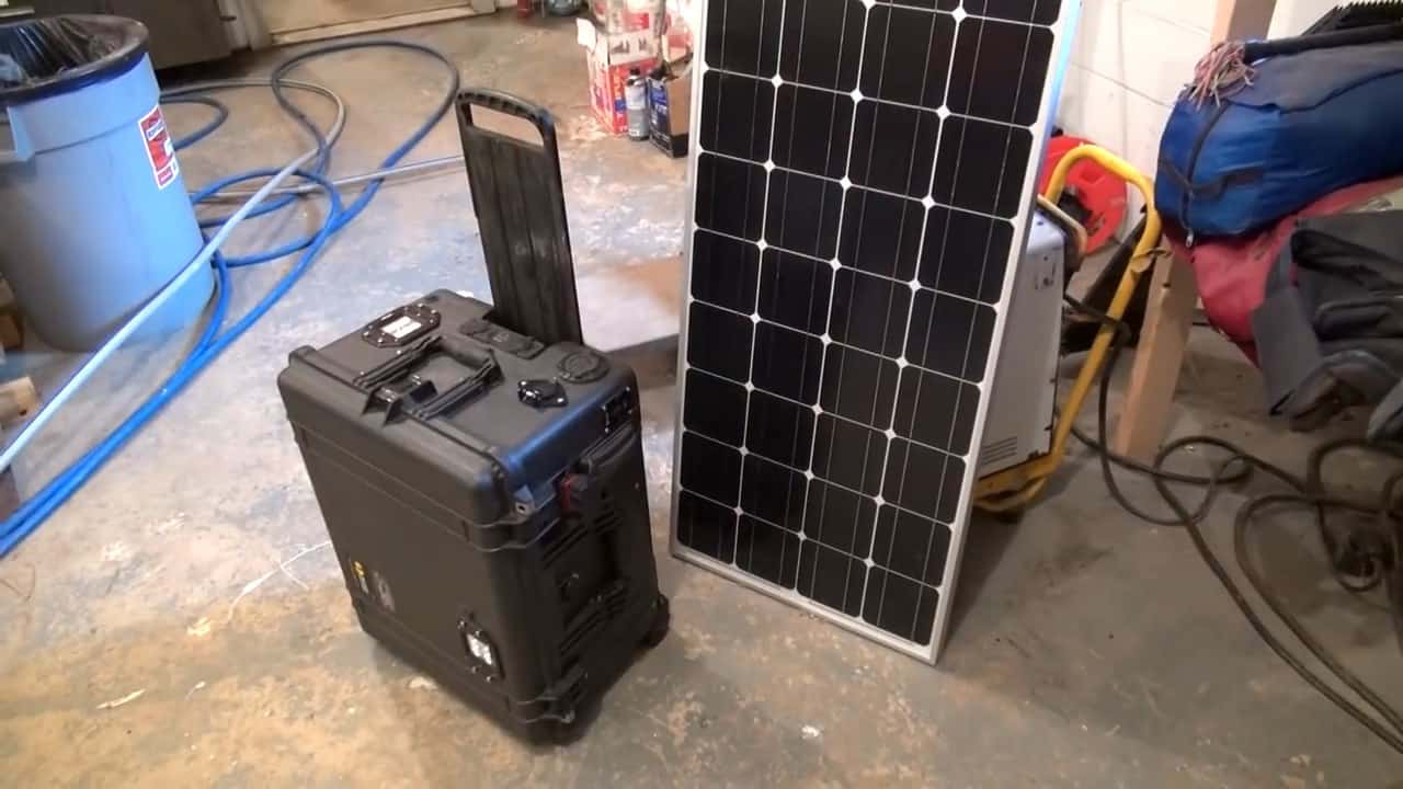
When selecting a solar panel for your portable solar generator, it is crucial to choose one that is reliable, efficient, and compatible with your system.
The Renogy 100W Solar Panel is an excellent choice for our large 2000W Portable Solar Generator, as it offers a range of features that make it well-suited for powering appliances ranging from small devices to larger power tools.
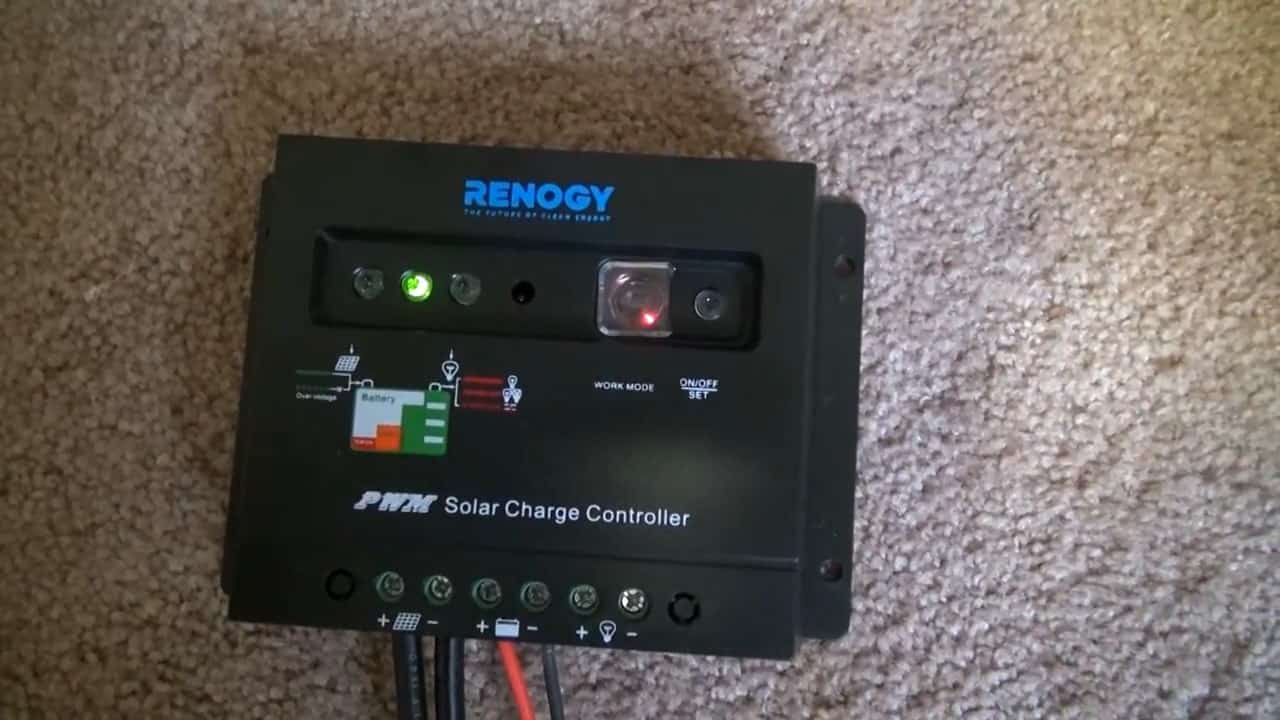
One of the key features of the Renogy 100W Solar Panel is its bus on the back, which allows for easy connection to your solar charger. Additionally, the panel comes with a 30A Solar Charge controller, which is designed to regulate the amount of charge that flows into your battery, ensuring that it is charged safely and efficiently.
With the ability to run up to four of the 100-watt panels in a 12-volt system, this charge controller provides you with greater flexibility in how you choose to set up your solar generator.
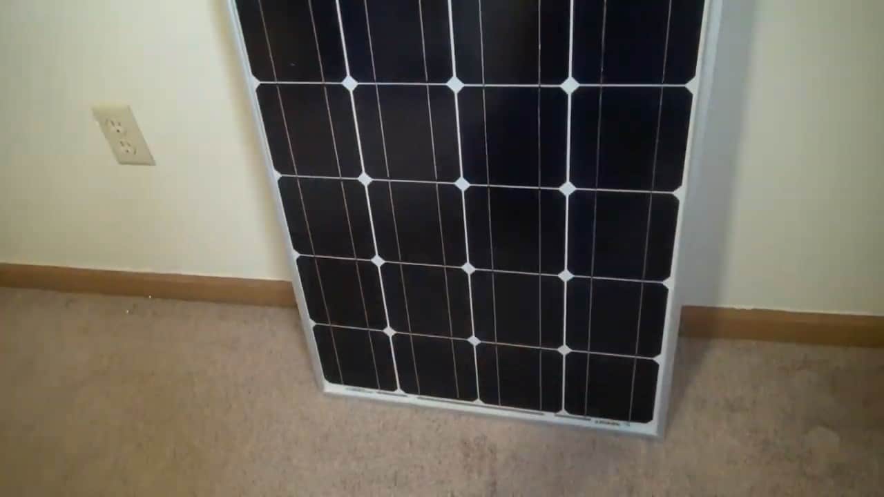
Furthermore, the back of the Renogy 100W Solar Panel comes pre-wired with MC4 connectors, which are a standard in the industry for connecting solar panels to one another or to a charge controller.
To extend the connection, we use high-quality 16 gauge speaker wire, which is highly flexible and ideal for portable use.
This wire is stripped of insulation and then crimped to the MC4 pigtails using butt splice connectors to ensure a secure and reliable connection.
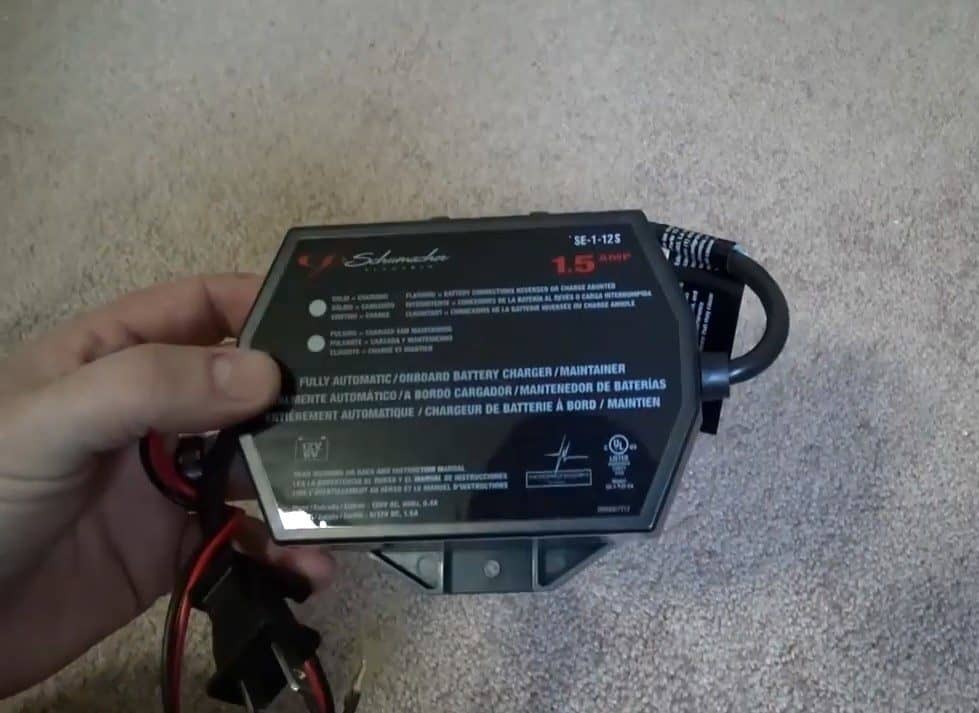
To provide an additional option for charging the solar generator, we have included a 1.5A Battery Maintainer/Float or Trickle Charger that can be powered by standard AC power.
This device is useful for maintaining the battery’s charge level when the system is not in use or when you do not have access to sunlight to recharge the system through the solar panel.
It is also suitable for quickly recharging the battery if necessary.
The 1.5A Battery Maintainer/Float or Trickle Charger is designed to prevent overcharging and prolong the life of the battery.
It uses a smart charging algorithm that adjusts the charging current based on the battery’s state of charge, so you can leave it connected without worrying about damaging the battery.
To use the Battery Maintainer/Float or Trickle Charger, simply plug it into a standard AC outlet and connect the output cable to the charging port on the solar generator.
The charging process will begin automatically, and the LED indicator on the device will show the charging status.
Once the battery is fully charged, the charger will switch to float mode to maintain the battery’s charge level and prevent overcharging.
STEP 4 : MOUNTING INTERNAL AND EXTERNAL COMPONENTS
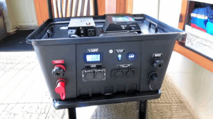
The next step in the build process involves mounting various external components onto the case. On one side of the case, we will mount a small LED work lamp that includes a toggle switch for easy operation.
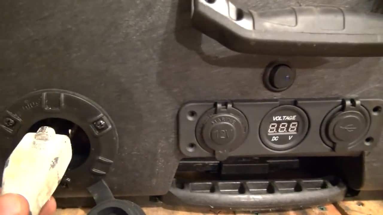
Additionally, a 12V gauge pod with a 5V USB output, a digital voltmeter, a 12V cigarette socket, an AC input plug for using with the trickle charger, and a 6-pin solar panel trailer connector will also be mounted.
These components are secured in place using RTV silicone sealant, which provides a strong and durable hold.
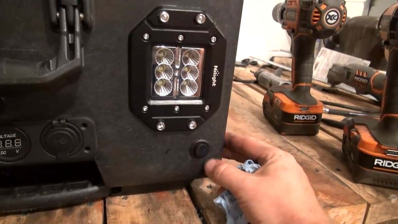
The LED work lamp provides a bright and efficient source of light, making it easy to work in low-light conditions. The gauge pod with USB output allows for convenient charging of devices such as smartphones and tablets.
The digital voltmeter provides an accurate reading of the battery voltage, while the 12V cigarette socket allows for the connection of various DC devices.
The AC input plug enables the use of the trickle charger for convenient charging when standard AC power is available.
Moving to the other side of the case, we will mount the inverter remote control switch, a 350A high current plug, and a GFCI AC outlet with a weatherproof cover.
The inverter remote control switch enables us to operate the inverter from a distance.
The 350A high current plug is used for jumper cables or to add high current loads to the system. The GFCI AC outlet is an essential safety feature that is designed to protect users from electric shock caused by ground faults. It is connected to the inverter inside the case
STEP 5 : INSTALLING THE BATTERY AND THE INVERTER
To optimize the portability of the solar generator, we strategically place the battery close to the wheels. By placing the heaviest component in the lower part of the case, it helps to maintain stability and balance when moving the case around.
To achieve this, we securely place the battery using a battery mount and two pieces of 2×4 wood.
To ensure proper functionality and safety of the solar generator, the inverter must be securely mounted inside the case.
To do this, we need to choose a location that allows for proper air ventilation to avoid overheating of the inverter. We also need to consider the wiring and make sure that there is enough space to tuck the wires underneath without any interference.
Once we have identified the ideal location, we can proceed with securing the inverter using mounting tabs and 10×24 machine screws.
These screws should be tight enough to hold the inverter firmly in place but not too tight that they damage the casing or the inverter itself.
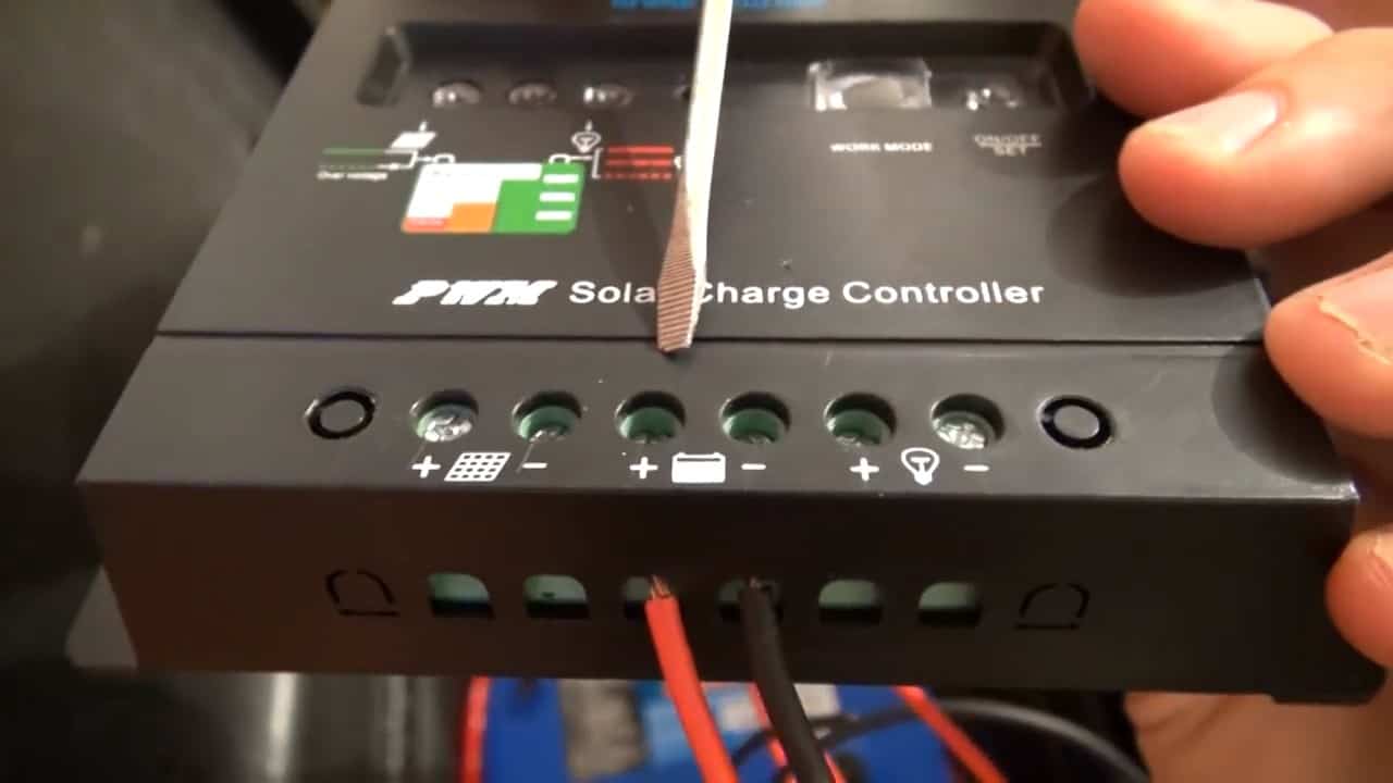
The next component to be mounted is the PWM solar charge controller, which is placed near the solar panel connector input. This location allows for easy access and monitoring of the solar power input and output.
The controller is secured in place using mounting tabs and 10×24 machine screws.
The charge controller regulates the voltage and current from the solar panel to ensure the battery is not overcharged or undercharged.
It also provides protection against overloading, short-circuiting, and reverse polarity.
To complete the assembly, the trickle charger/battery maintainer is mounted as low into the back of the case as possible. Given that it doesn’t generate much heat, we don’t need to worry about heat dissipation.
The power cord from the trickle charger is then plugged into the AC input cord on the exterior of the case.
This setup ensures that the batteries remain charged and maintained even when the solar panels are not in use.
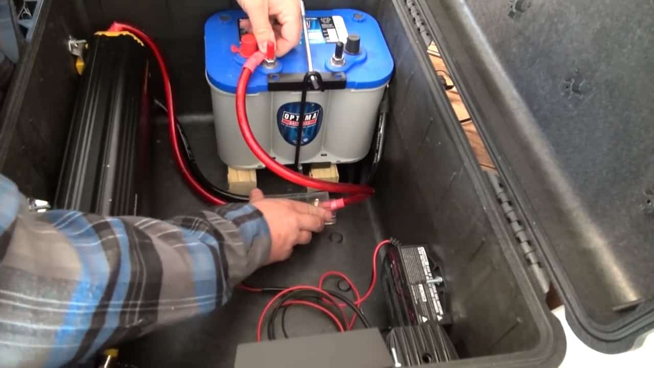
STEP 6 : THE WIRING
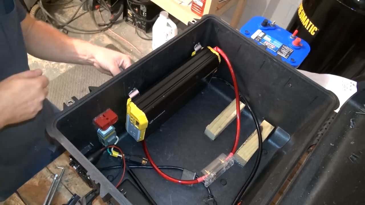
In this step, we will be wiring the components of our solar generator. We begin by connecting the power cables from the inverter to the battery.
It is important to connect the positive and negative from the inverter to the corresponding terminals of the battery. This ensures that power is correctly distributed from the battery to the inverter.
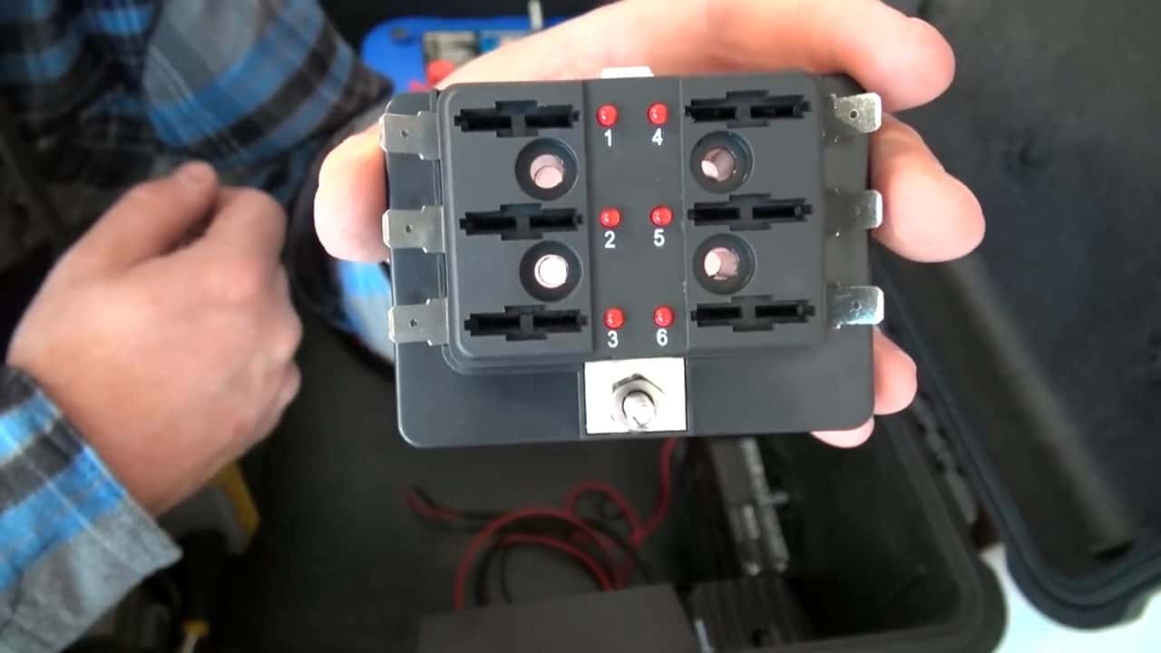
To distribute power in our generator, we use a six-circuit fuse panel for the positives and a busbar for the grounds. The fuse panel is used to protect the wiring and components from short circuits and overloads.
The positive wires from the battery are connected to the positive terminals on the fuse panel. Each circuit on the fuse panel is protected by a fuse, which should be selected based on the maximum current that circuit will draw.
The busbar is used for the negative connections of the components. The negative wires from the components are connected to the negative terminals on the busbar.
This ensures that all of the components share a common ground and reduces the risk of ground loops.
To ensure proper distribution of power in our solar generator, we use two high-quality battery cables that can handle high currents without overheating.
We connect one end of each cable to the positive and negative terminals of the battery, respectively. The other ends are used to power the distribution blocks and the high current quick connector.
The red positive connector from the quick connector is connected to the positive side of the six-circuit fuse panel, which allows us to control and distribute power to different circuits.
On the other hand, the black negative connector is connected to the ground busbar, which serves as the common ground for all the components in our solar generator.
Both connections are further extended to connect to the positives and negatives of the battery respectively.

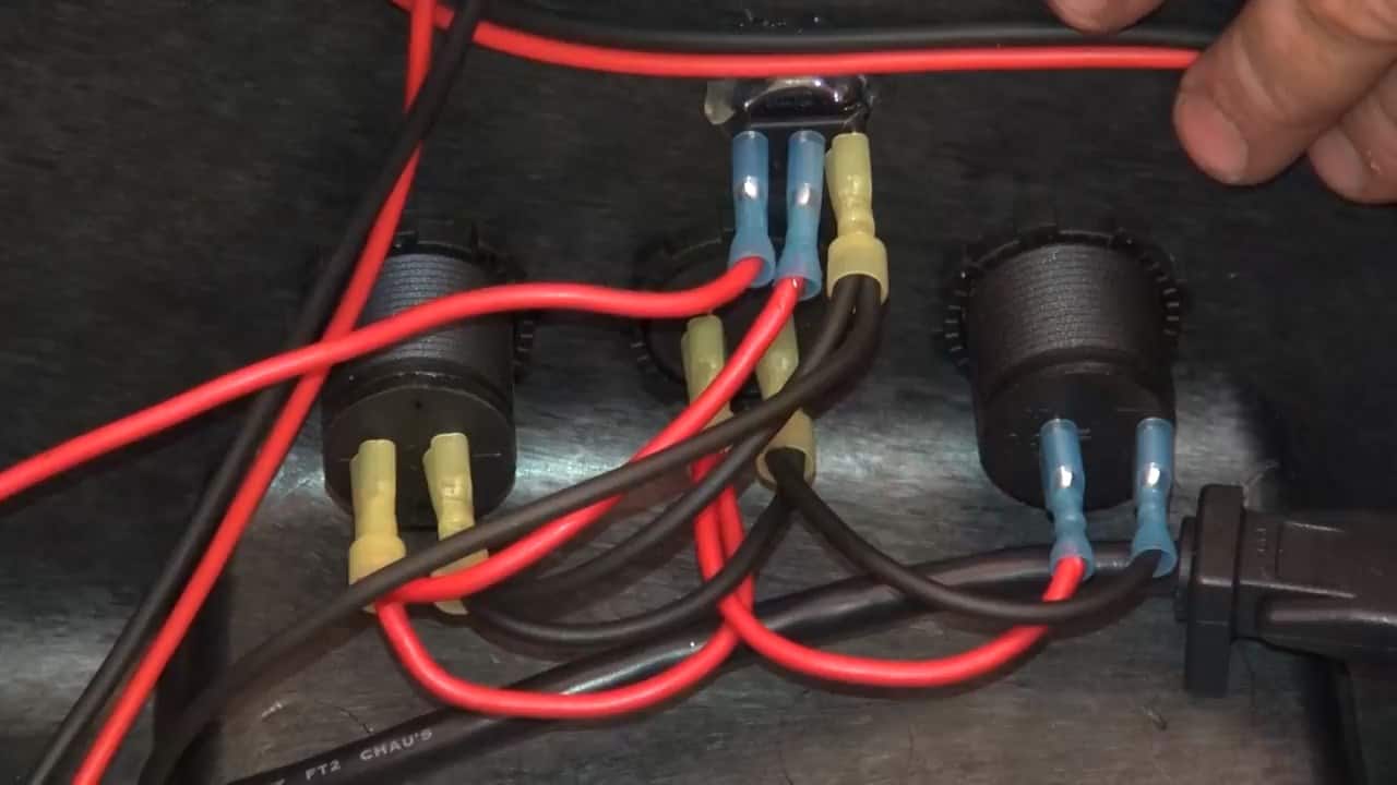
The LED lights are connected to the 3-way connector switches. These switches are rated for 12V DC and can handle up to 20A.
The switches are further connected to the power distribution fuse block which houses individual fuses for each circuit. This adds a layer of protection in case of any electrical faults or overloads.
Similarly, a single switch is connected to the USB outlet, voltmeter, and cigarette lighter ports in parallel. This switch is rated for 10A and is also connected to the power distribution fuse block for added safety.
The positive from the switch is connected through a daisy chain mechanism to the three positives of the ports while the negatives are similarly connected to our distribution block.
Now that we have connected all the components to the main power source, it’s time to organize and bundle the wires. We want to ensure that the wires are neat and tidy, so we use zip ties to secure them.
Additionally, we separate the positive wires from the negative wires to make it easier to connect them to the distribution blocks.
Once we have all the ground wires connected to the ground busbar, we can move on to the power wires. Each blade connector on the distribution block represents one fuse circuit.
To ensure proper connection, we connect the positive red wires from the charge controller, battery trickle charger, USB ports, voltmeter, and 12V outlet to the respective fuse circuits.
We use a 30A fuse for the charge controller and 12V socket, 20A for the LED work lights, and 5A for the trickle charger. By using different fuses, we can ensure that each circuit is protected from any electrical overload.
Image Credits : ModernSurvivalists