Crafting your own solar generator is a practical way to harness renewable energy while gaining independence from the grid. This DIY project offers a cost-effective, customizable solution for various power needs, from camping trips to emergency home backup. This guide will walk you through the steps to build your own solar power system, perfect for a small workshop, shed, RV, power lights, fans or as a backup power source in emergencies. This system is designed to be expandable, allowing you to increase capacity as your needs grow.
STEP 1 : THE MATERIALS REQUIRED
-
Battery: 100Ah LiFePO4 battery(Ampere Time 12V 100Ah LiFePo4 Battery)
- Mounting Panel : Half Inch Think Plywood
-
Charge Controller: 40A MPPT solar charge controller ( BougeRV 40A Charge Controller)
- Solar Panel : BougeRV 200W Solar Panel
-
Inverter: 2000W pure sine wave inverter (12V input) (Novopal 2000W AC Inverter)
-
Battery Cables: 8 gauge battery cable (length will depend on your setup)
-
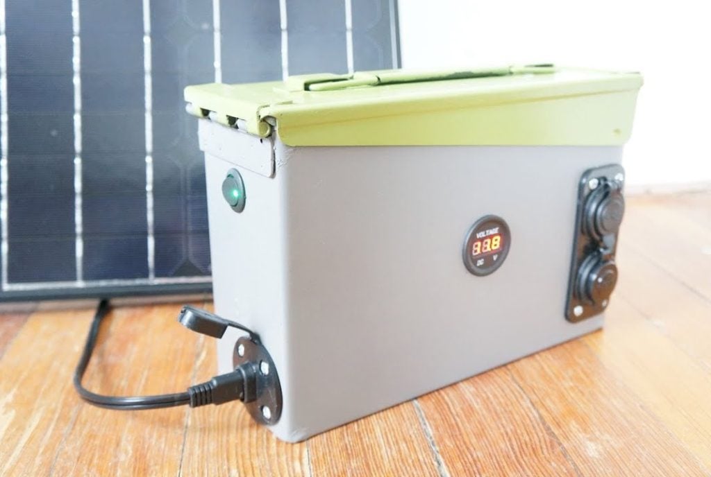
DC Panel with Outlets: 12V DC panel with USB Ports and a voltmeter
-
Fuses/Circuit Breakers: 200A and 50A circuit breakers (or equivalent fuses)
-
Terminal Connectors: Appropriately sized copper connectors for your cables
-
Heat Shrink Tubing: For insulating terminal connections
-
Miscellaneous: Large Gauge Cable Crimper & Cutter,Large Gauge Cable Stripper,20ft 8AWG MC4 Solar extension cables,Cable Mgmt Clips,Multimeter/Clamp
STEP 2 : Prepare the Mounting Panel

Use a piece of plywood as the base for your components. Here we use a half inch thick plywood. Determine the location for your charge controller, inverter, and 12V Accessory ports.
Measure and mark positions for all components on the plywood .Securely mount your charge controller, inverter, DC ports, and fuses/circuit breakers to the mounting board.
The 50A Breaker sits between the Charge Controller and the Inverter and the 200A breaker that is mounted just below the inverter for further connecting it with the battery.
STEP 3 : Wire the System

-
Positive Wiring (Red):
-
Connect the positive terminal of the battery to the positive terminal of the 200A circuit breaker.
-
Connect the other terminal of the 200A circuit breaker to the positive terminal on the inverter.
-
Connect the positive terminal of the inverter to the positive terminal of the 50A circuit breaker.
-
Connect the other terminal of the 50A circuit breaker to the positive terminal on the charge controller.
-
-
Negative Wiring (Black):
-
Connect the negative terminal of the battery directly to the negative terminal of the inverter.
-
Connect the negative terminal of the inverter to the negative terminal of the charge controller.
-
-
Solar Panels:
-
Wire the positive and negative terminals of your solar panel(s) to the input terminals of the charge controller. Make sure to use appropriately gauged wire for the expected amperage from your solar panel(s).
-
STEP 3 : Connecting the DC Accessory Ports

All the positive terminals of the DC ports are wired together in parallel. Similarly, all the negative terminals of the DC ports are wired together in parallel.
 +
+
Positive Connection: The red wire from the DC panel’s positive terminal is connected to the positive terminal of the 50A circuit breaker. This means the power to the DC accessories first goes through the 50A breaker for protection.
Negative Connection: The black wire from the DC panel’s negative terminal is connected to the negative terminal of the inverter. This creates a common ground with the inverter’s negative terminal.
Before connecting to your solar panels, energize the system by switching on the circuit breakers. Test the output voltage of the inverter using a multimeter.
STEP 4 : Connecting the Battery and testing the System
Attach main positive and negative leads to the battery terminals.Before connecting to your solar panels, energize the system by switching on the circuit breakers.

Test the output voltage of the inverter using a multimeter.Before final closure, test each component.Turn on the inverter and check its display for proper voltage reading.Check voltage readings on DC ports and compare with a multimeter for accuracy.Test the charge controller power-up sequence
STEP 4 : Connecting the Solar Panels and Final testing

Once your system is wired and tested, connect your solar panels to the charge controller via the Anderson Connector. The positive (+) wire from the solar panel would be connected to the positive (+) input terminal of the MPPT charge controller.
The negative (-) wire from the solar panel would be connected to the negative (-) input terminal of the MPPT charge controller.Monitor the charge controller display to ensure the panels are generating power and the battery is charging using the bluetooth App that comes with the charge controller.

Connect various AC loads to the inverter (like a hair dryer) to test under different power draws. Test DC loads (like a 12V refrigerator) on the DC outlets. If planning to add batteries later, ensure enough space on your panel.Consider upsizing cables and breakers now if you plan to expand significantly later.Leave room for additional solar panel connections on your charge controller.
Image Credits : ReeWray Outdoors