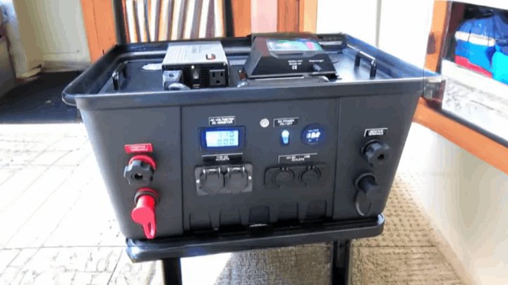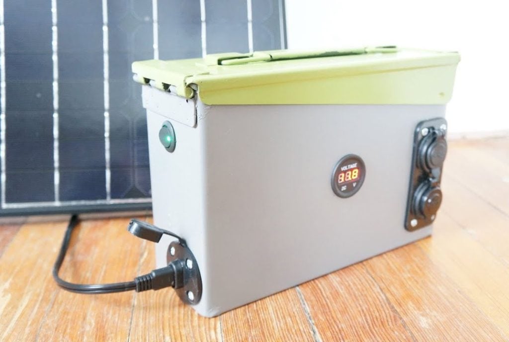
Hurricanes and other natural disasters can leave you without power for days or even weeks. A solar generator can provide you with backup power to keep your essential appliances running. In this article, we’ll show you how to build your own DIY lithium solar generator using a Stanley 50-gallon toolbox.
The primary goal is to have a reliable battery bank that can be used as a backup power supply in the event of a power outage.The configuration should be portable, safe, and secure. Using a lockable toolbox helps achieve all three of these goals.Also,this battery bank should be able to power a full size refrigerator/freezer and a 7 cubic foot chest freezer for over 48 hours without recharging.
STEP 1 : MATERIALS REQUIRED
-
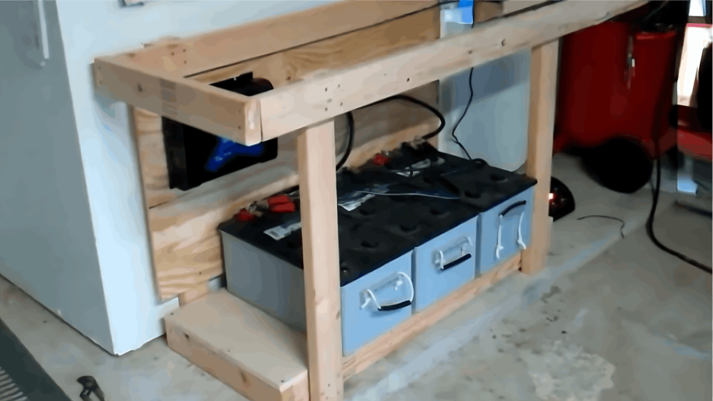
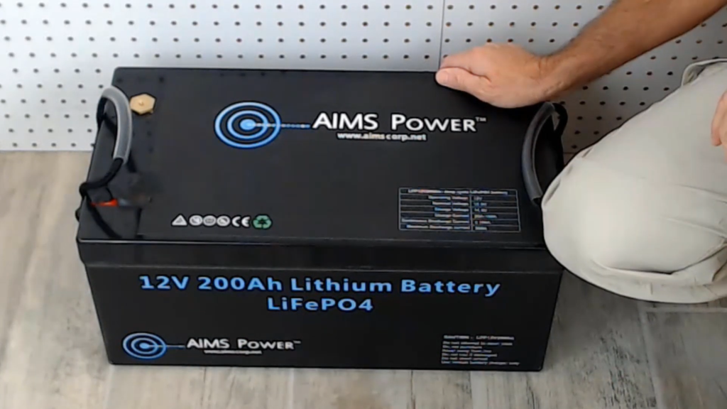
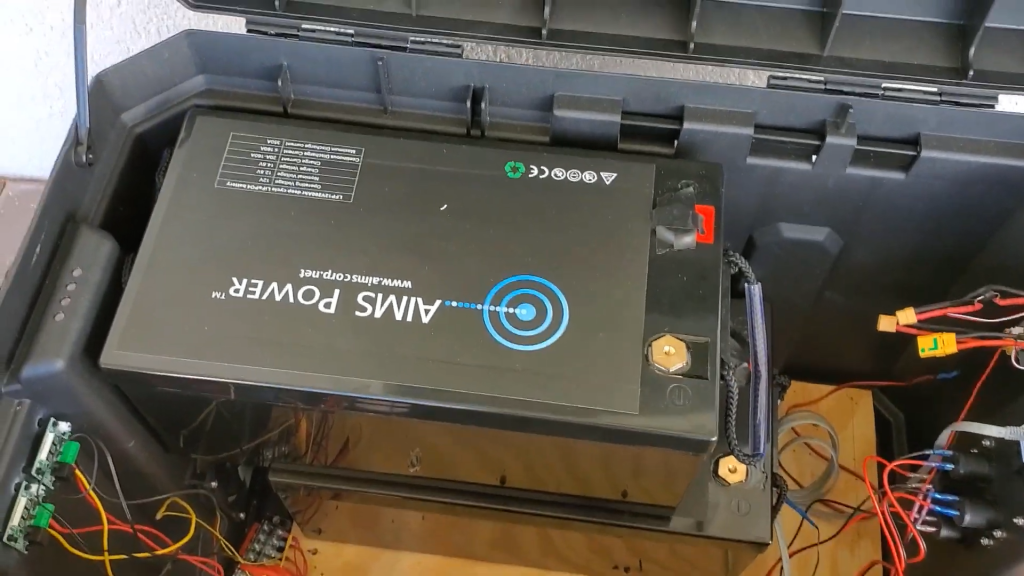
Battery Bank: Two LifePO4 12V 200Ah Aims Power lithium batteries (or equivalent) . The two batteries are combined in series to get a total of 24V or a total of 4800Wh.
-
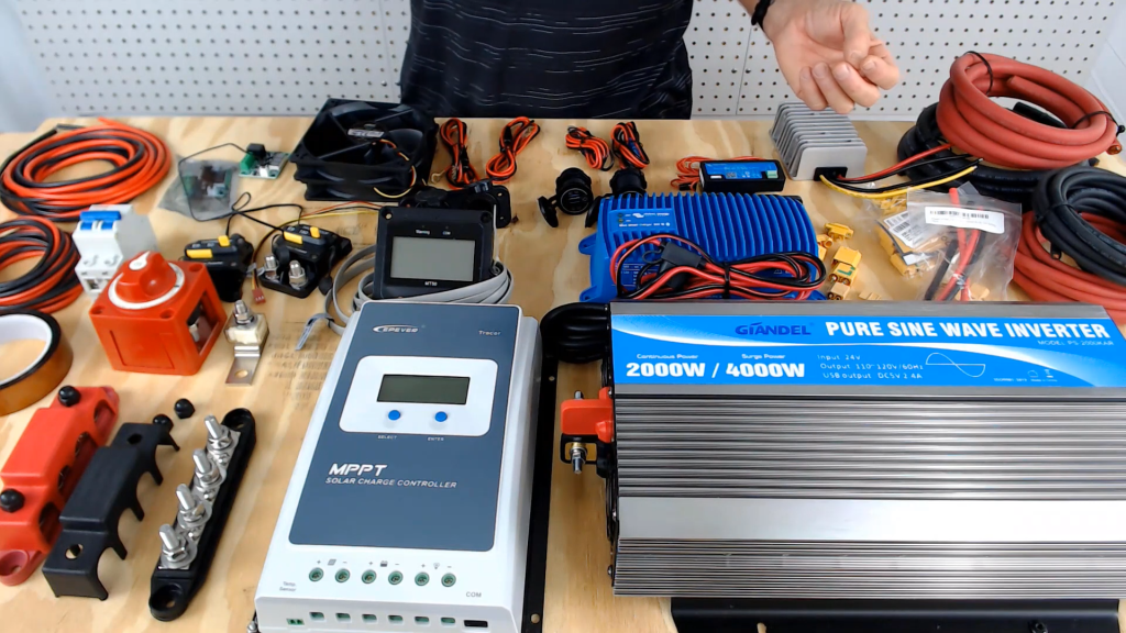
Inverter: 24V 2000W Giandel pure sine wave inverter . The inverter has two outlets, which is exposed on the outside of the toolbox. In addition to the outlets, the inverter has a digital display and the on-off button
-
Solar Charge Controller: 100V input, 24V output, 40A MPPT solar charge controller .The charge controller is rated for up to 40 amps at 24 volts or 960 watts. Here we use eight solar panels that are 100 watts each.With four panels in series and then the four panel sets connected in parallel. This configuration results in a nominal voltage output from the panels of 72 volts at 11.2 amps.The solar panels are rated for 18 volts at 5.6 amps each. This means that each panel can produce a maximum of 100.8 watts.The nominal output of the 8 panels is 800 watts. The maximum output of the panels is actually close to the 960 watts, so the charge controller is a good match.
-
DC–to–DC Converter: 24V to 12V step–down converter .This powers 2 12V accessory ports,2 USB 3.0 fast charing ports,2 120mm cabinet fans.
-
Shunt: Victron SmartShunt for montioring the battery bank using phone
-
AC–to–DC Charger: 120V input, 24V output Victron Blue Smart IP67 charger
-
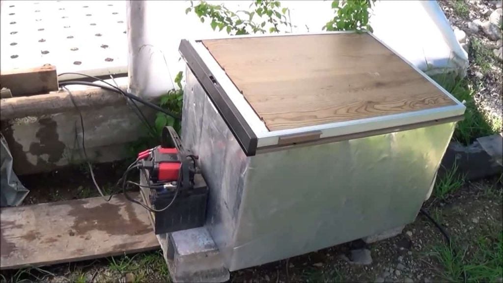
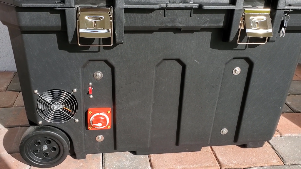
Toolbox: The Stanley 50 toolbox has several features that make it ideal for this project, including two wheels, an extendable arm for leverage, two over-centered latches, and a keyed lock. The toolbox is also rated for 110 pounds, which is slightly over the weight of the finished solar generator.
-
Other: MT50 display unit for the charge controller,plywood, Tnuts, screws, fender washers, threaded rod, XT60 connectors, temperature sensors, bus bar, fuses, circuit breakers, and a switch
STEP 2 : PREPARING THE TOOLBOX

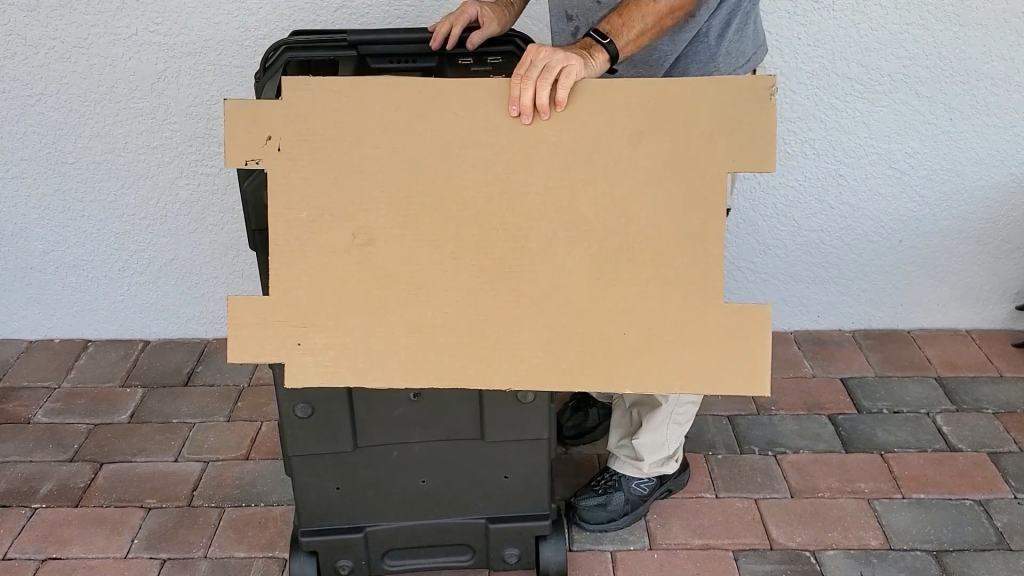
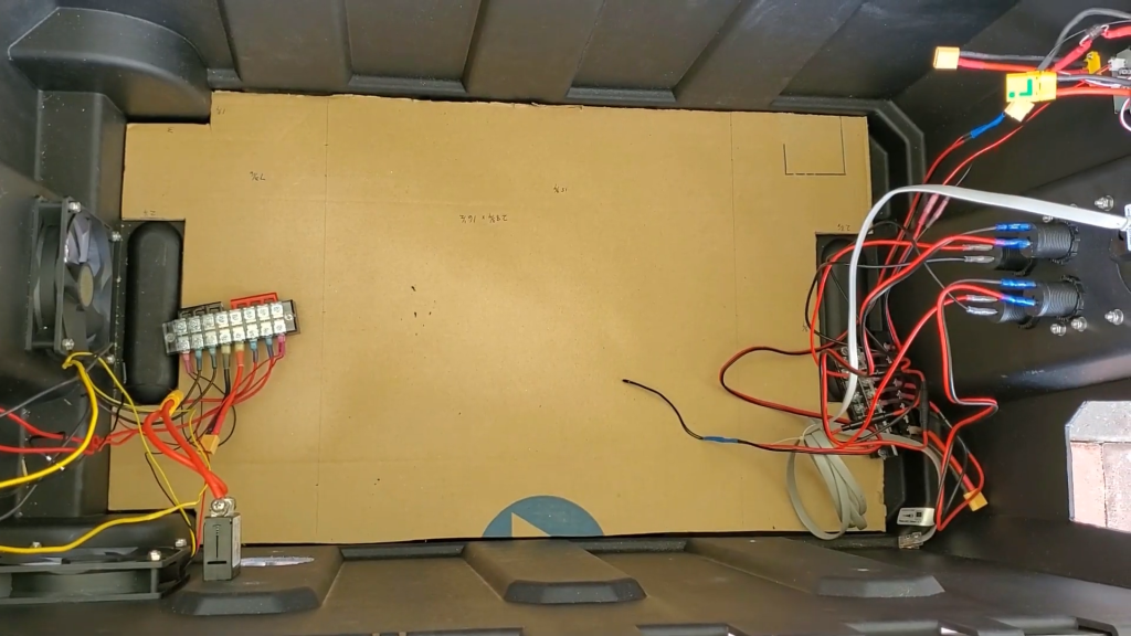
Remove the lid and any trays from the toolbox. Drill six holes in the bottom of the toolbox to mount the plywood base .Cut out sections of the cardboard template to fit around the wheel wells and raised areas inside the toolbox
Transfer the hole locations from the cardboard template to the plywood base .Install T nuts in the plywood base at the hole locations.Secure the plywood base to the bottom of the toolbox using screws and fender washers
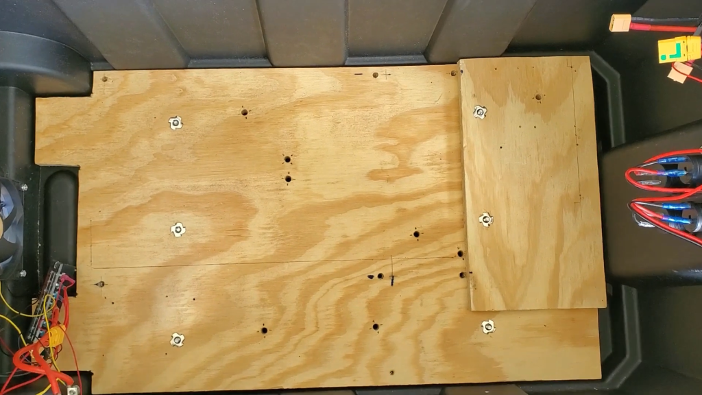
The raised part on the right helps secure the battery ,keeping them wedged between the plywood and the wheel well on the left.
STEP 3 : INSTALLING THE BATTERY
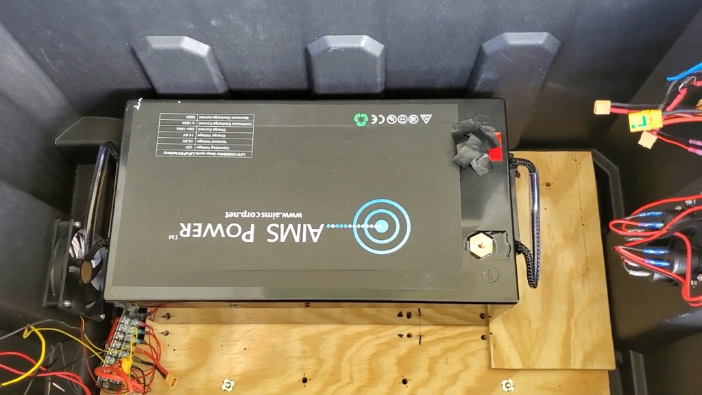
Place the first battery in the toolbox, ensuring it rests against the plywood base and the wheel well. This will help to keep the battery in place.
The second battery is placed on top of the first battery . Ensure that the batteries are placed such that we have enough space for installing the charge controller and the inverter.
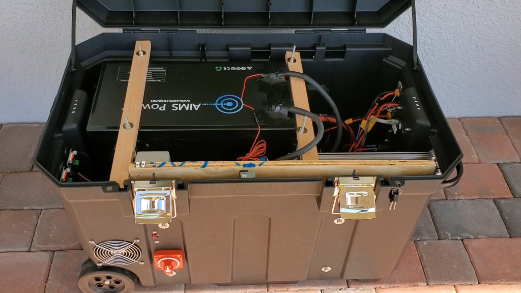
STEP 4 : PLACING THE DAUGHTERBOARD
Cut another piece of 3 and 1/4 plywood to fit against the longwall of the toolbox.This will be the daughterboard.Make sure the plywood is thick enough to support the weight of the components.
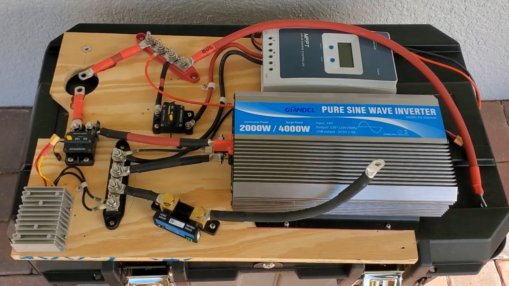
Mount the busbar,amp breakers, inverter,charge controller,DC–to–DC converter,shunt,and AC–to–DC charger onto the daughterboard.The inverter is connected to the battery bank through a 150amp circuit breaker. This breaker protects the wire going from the battery bank to the inverter.
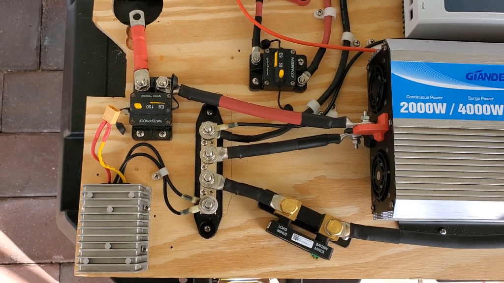
The charge controller is connected to the battery bank through a 50 amp circuit breaker.The bus bar is used to connect the positive terminals of the batteries together. This allows for a single connection point for the positive terminal of the battery bank, which simplifies the wiring and makes it easier to connect other components to the system.
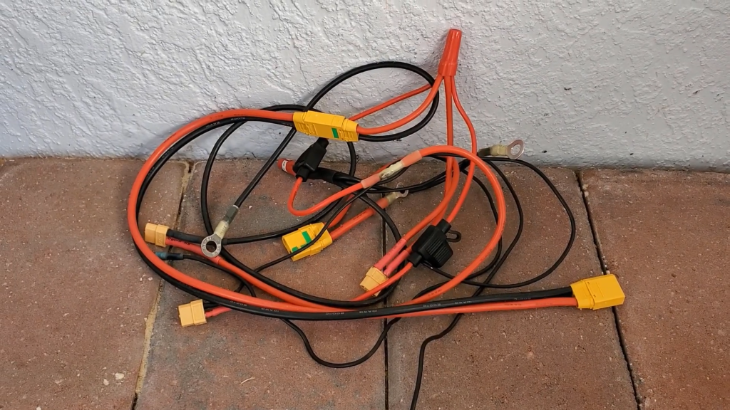
The DC–to–DC converter is connected to the 12–volt bus bar in this system.This is used to step down the 24-volt battery bank voltage to 12 volts.An XT60 connector using a wiring harness allows the system to power a variety of 12-volt devices, such as usb ports,sensors and displays.
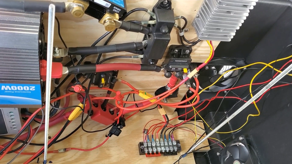
Secure the daughterboard to the side of the toolbox using four bolts and fender washers.The wiring harness is used to connect all of the 12–volt circuitry in the solar generator system. This includes the DC–to–DC converter, the two 12–volt auto–accessory plugs, the two USB 3.0 fast–charging ports, and the two 120–millimeter cabinet fans.
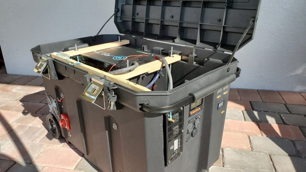
STEP 5 : SECURING THE BATTERIES
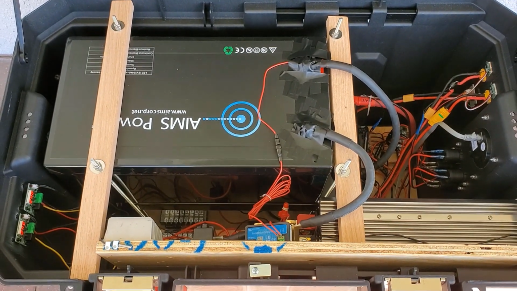
The batteries are secured in place with two piece of 1X 2 Oak wood using 4 threaded rods. The front 1X 2 is securing the top battery from moving up and down and going forward,backwards.
STEP 6 : EXTERNAL CONNECTORS
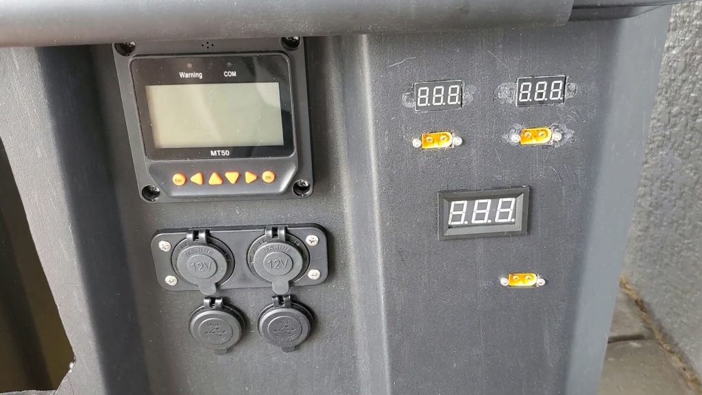
The external connectors include the temperature display which reads the temp using probes placed in the box. 24V IN to charge up the battery in case of an alternate source for charging the batteries. Additional connectors include a MT50 interface for the charge controller,12V car accessory jack,USB ports.
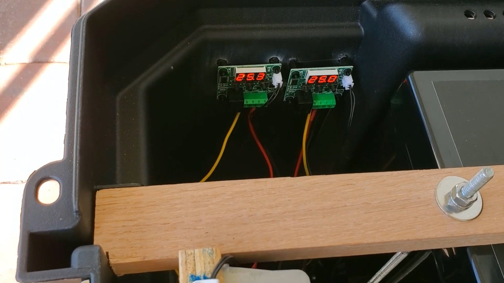
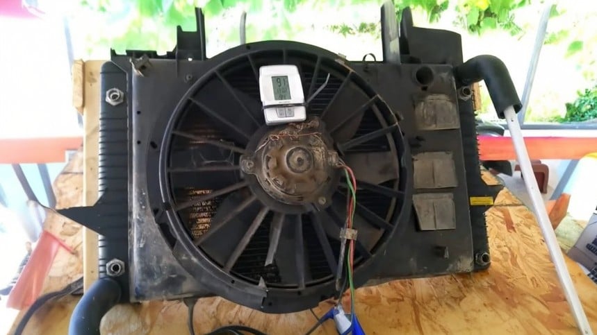
The Temperature sensors are used to control the fans. One of the probes are located near the DC-DC convertor, the other near the inverter
Image Credits : DIY Lithium Solar