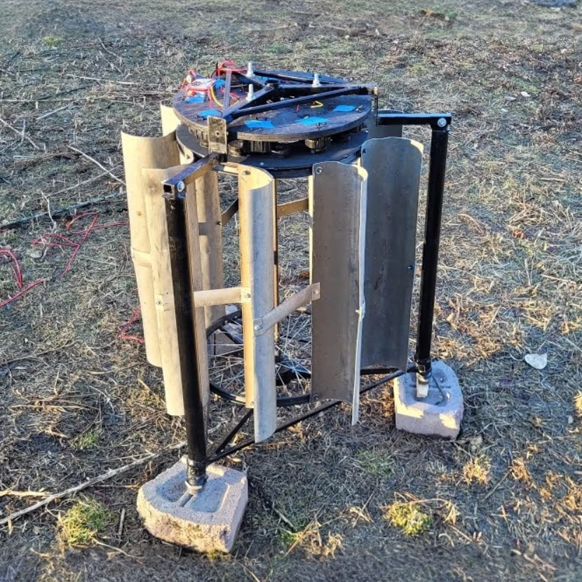
This is a DIY vertical axis wind generator assembled almost entirely from salvage. Thirteen dead microwave ovens supply the magnets and the coil windings. The bearings come from two child size bicycle wheels, and the frame is 1 inch square steel tubing with scrap fence tubing making up the rest.
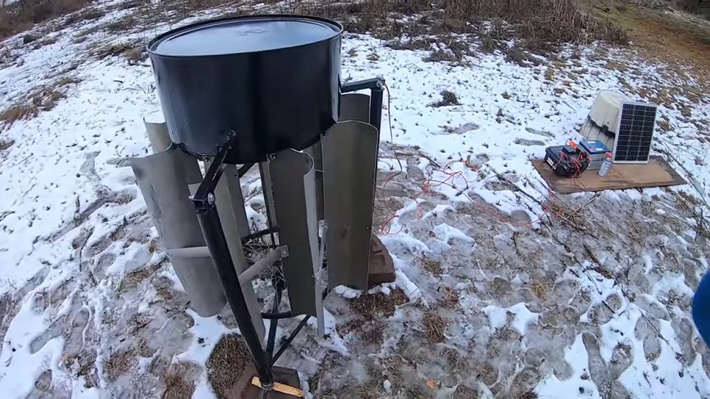
The whole setyp runs nine coils against twelve stacked pairs of ring magnets, wired as a three phase star and rectified to DC inside an Altoids tin. Spun by hand the output climbed to 15.7 volts, which works out to a good solid moderate wind.
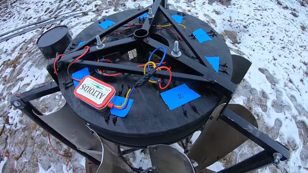
The finished machine runs nine coils against twelve stacked pairs of ring magnets, wired as a three phase star and rectified to DC inside an Altoids tin. Spun by hand the output climbed to 15.7 volts, which works out to a good solid moderate wind.
Step 1 : The Materials Required
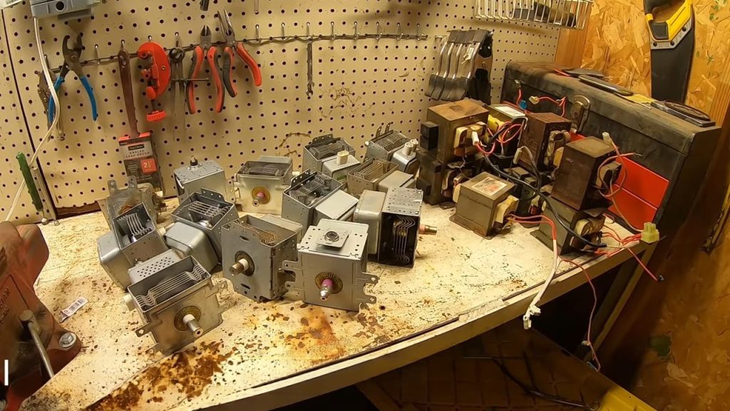
- 13 scrap microwave ovens, for the ring magnets, transformer cores and windings
- Two child size bicycle wheels
- 1 inch by 1 inch square steel tubing, just under 10 feet
- 3/4 by 3/4 inch square steel tubing, salvaged fence
- 1/4 inch plywood for the rotor disc
- 3/4 inch plywood for the stator, pallet wood works
- Construction adhesive
- Black vinyl electrical tape
- Heat shrink tubing
- Zip ties
- Wood screws
- Cotter pins
- Bolts and assorted hardware
- 14 gauge bonded wire
- Six Schottky diodes and a 50 volt capacitor
- An empty Altoids tin
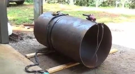
- A 55 gallon drum for the cover
- Angle grinder
- Drill
- Hammer
- Bench vise
- Pliers and side cutters
- Screwdrivers
- Soldering iron
- Wire strippers
- Heat gun or lighter
- Multimeter
Step 2 : Stripping the microwave ovens
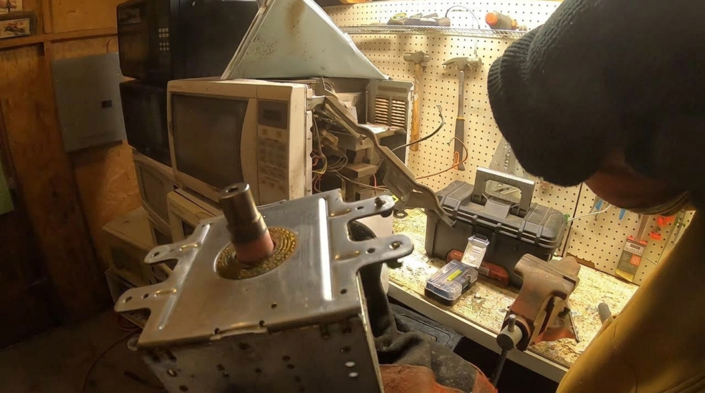
Unplug the oven from the wall before the case comes off. The first job on every unit is then to arc the capacitor contacts safely and disconnect the leads, working with leather gloves and insulated tools before you touch anything else inside the cabinet. Check the capacitor across its terminals with the multimeter before you reach in, so you know it is discharged rather than assuming it. 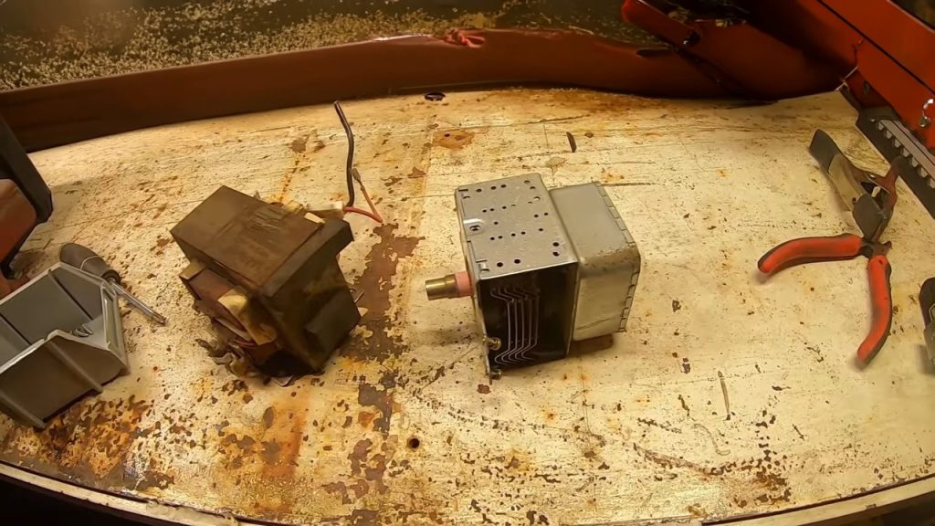
Once the cabinet is dead, the shell comes apart and the components lift out. Every oven mounts things differently, but the transformer, the magnetron and the capacitor are generally held by a handful of screws
Step 3 : Harvesting the ring magnets
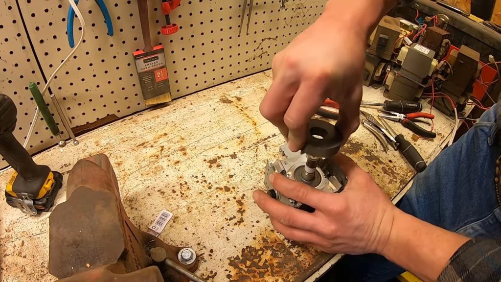
Each magnetron holds two ferrite ring magnets inside its steel housing. The housing is broken open on the bench and the magnets are pried free. Thirteen ovens yield 26 magnets, and this build consumes 24 of them in twelve stacked pairs, leaving a spare pair.
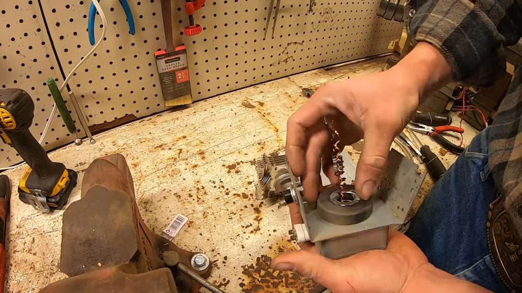
The ceramic insulator inside a magnetron is the part to treat with care, because it may contain beryllium oxide. You cannot tell which ceramic you have by looking at it, so do not break, grind or sand it, and dispose of the carcass safely once the magnets are out.
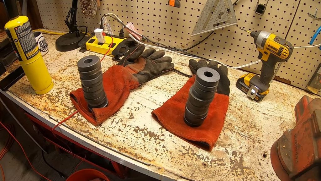
Step 4 : Cutting the transformer cores open
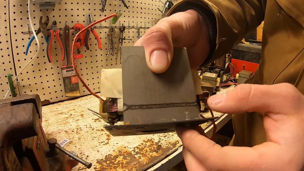
The laminated cores are welded along their seams, and those welds have to be cut before the windings will come out. An angle grinder run down each seam is enough to release the stack without cutting into the copper or aluminum underneath.
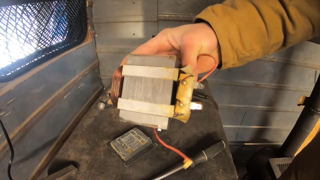
Cut only as deep as the weld bead. The laminations themselves are thin and the windings sit directly behind them, so a heavy cut destroys the part you are trying to harvest.
Step 5 : Extracting the secondary windings
With the seams cut, the core is clamped in a vise and driven apart with a hammer until the coils drop free. The windings are fragile. All of the force goes into the iron and never into the wire bundle itself.
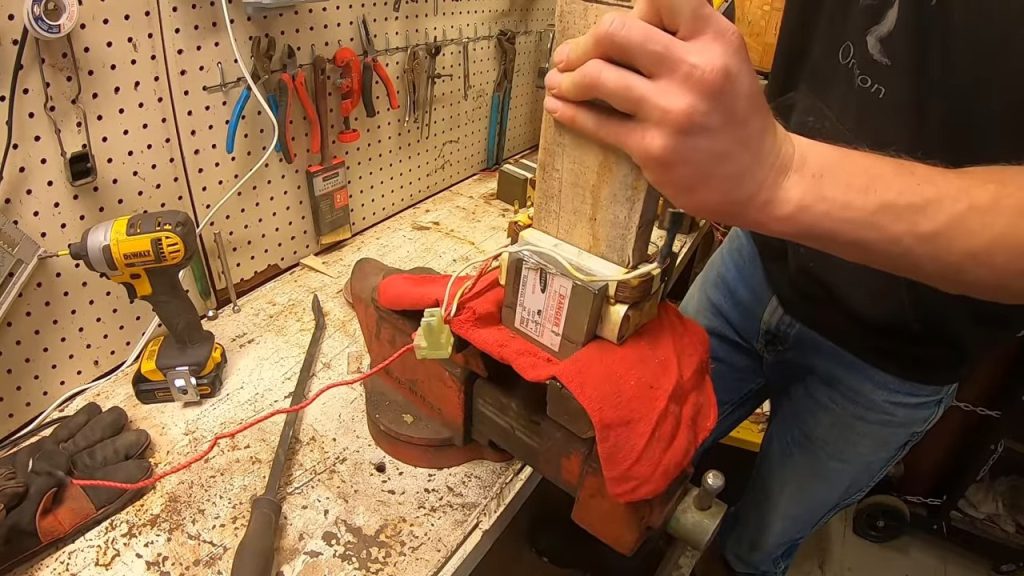
The secondary coils are the ones worth keeping. They carry many more turns of much thinner wire than the primary, and more turns generate a higher voltage for the same movement of the magnets, though the thinner wire limits how much current the coil can carry. Many microwave transformers you will find in the wild are aluminum wound, which is workable but less desirable than copper.
Step 6 : Extending and insulating the coil leads
The original terminals are short, so each coil gets its leads extended to a usable length for wiring nine coils into three phases. Every joint on this generator is soldered.
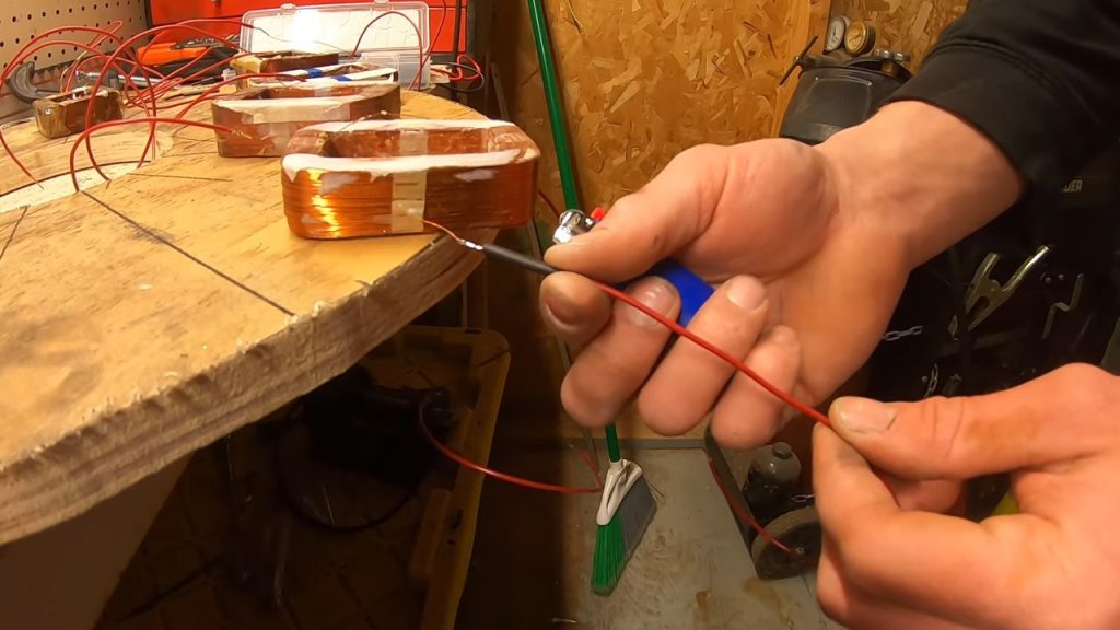
Heat shrink tubing over each lead keeps the bare wire clear of the neighboring coils and the wooden holders. Thin secondary wire chafes easily, and damaged insulation inside a phase group can produce a short or a fault.
Step 7 : Wrapping the coils
Each finished coil is wrapped in black vinyl electrical tape with its two output wires left proud. The tape holds the winding bundle together and gives the coil a clean outer surface to sit against a wooden holder.
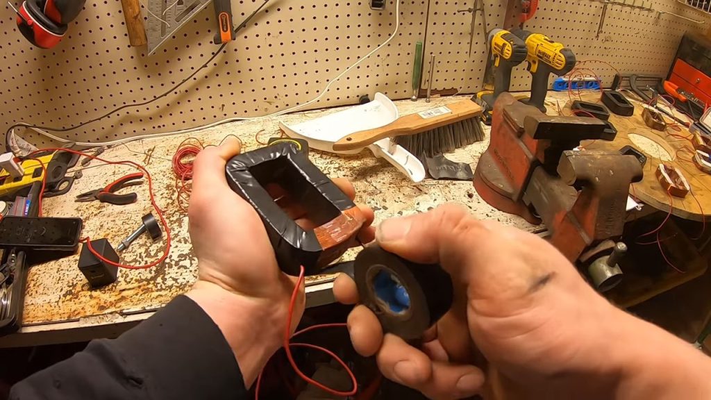
Mark which wire comes from the center of the coil and which comes from the outside before you tape it. That distinction decides how each coil connects to the next when the phases are wired, and working it out afterwards means unwrapping the tape or testing the leads, which is a nuisance you can avoid.
Step 8 : Setting the magnet positions on the rotor
The rotor disc is a circle of 1/4 inch plywood bolted down to the top of the upper bicycle wheel. It is the part with the magnets, and it is called the rotor because it spins.
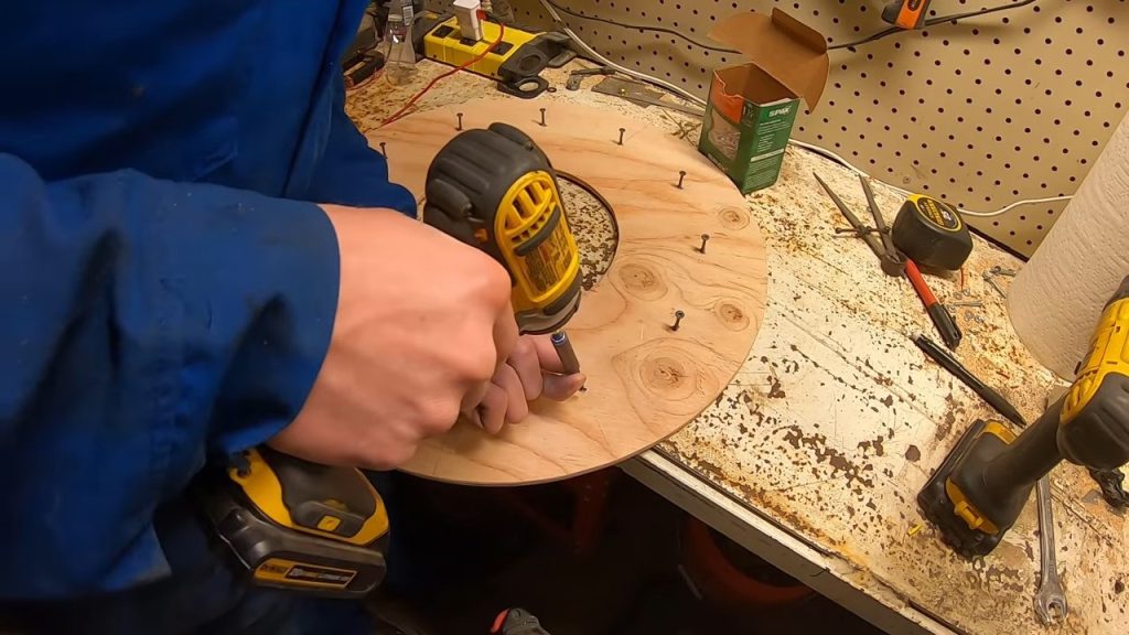
Twelve magnet positions are laid out around the disc and a wood screw is driven into the center of each one. The screws fix where the magnets go, and each magnet is then centered by hand over its screw before the adhesive sets.
Step 9 : Bedding the magnets in adhesive
Each stacked pair of magnets drops over its centering screw and the remaining gap is filled with construction adhesive that dries hard. Gravity carries the weight of the magnets, so the adhesive only has to stop them creeping sideways.
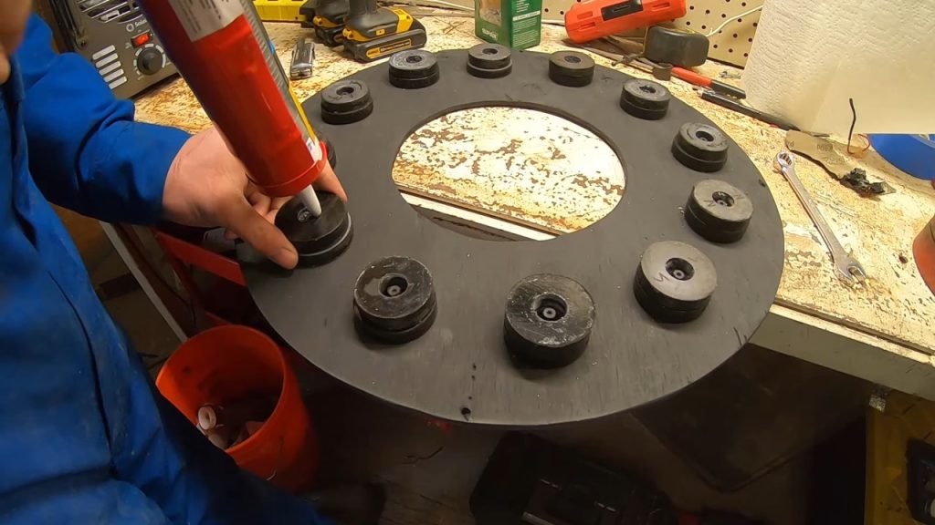
Set the pairs in alternating polarity, north facing up, then south, then north, all the way around the disc. That alternation is what makes each coil see a reversing field as the rotor turns, and it is what produces alternating current in the windings.
The build originally used a single magnet in each position. Two stacked magnets per position put more magnetic lines of flux through the gap, and the plywood disc was switched to a thinner sheet to suit.
Step 10 : Making the coil holder blocks
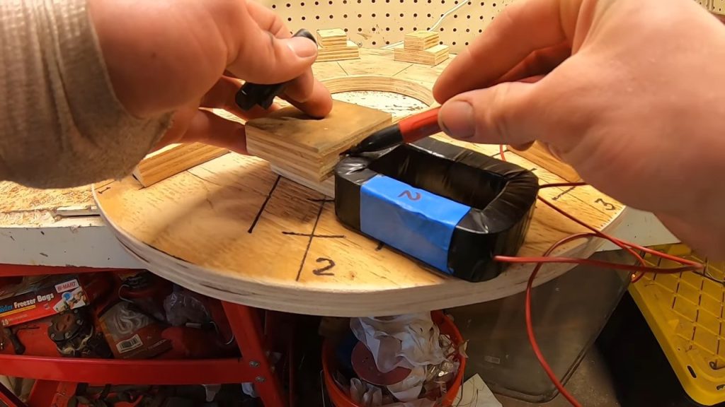
Salvaged transformer coils are not identical, so each one needs a holder cut to fit it. The blocks are laminated from scrap wood and then shaped in the vise, each one sized against the coil it will carry.
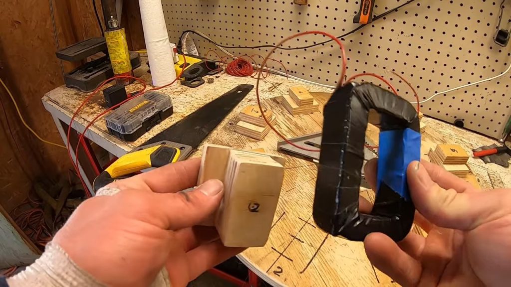
Wood is the right material here for an electrical reason. Steel sitting close to the passing magnets causes cogging, a magnetic notching that fights rotation, so keep metal out of the stator wherever a wooden part will do the same job.
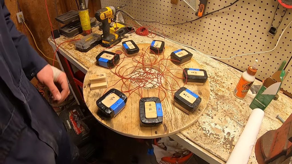
Step 11 : Fitting the coils to the stator
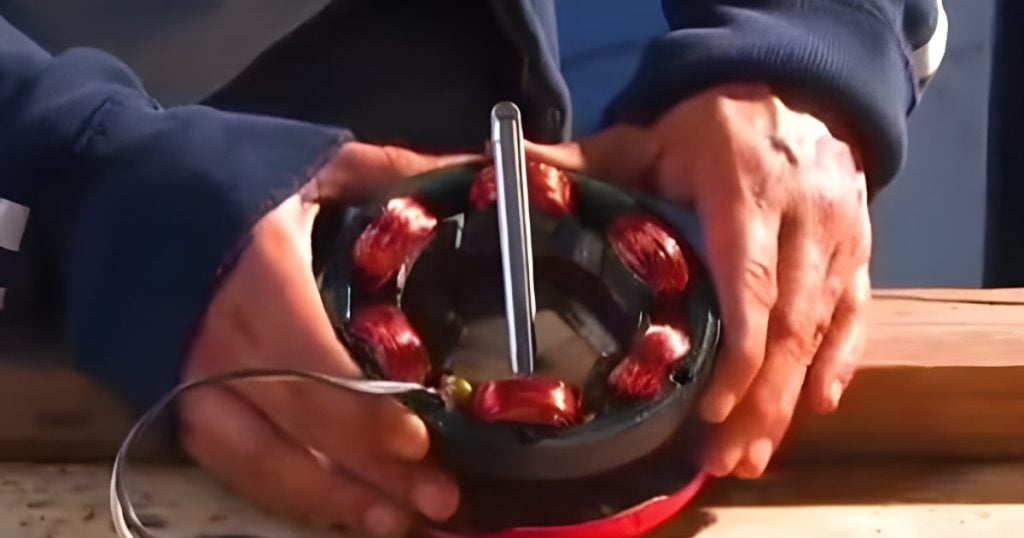
The stator is the stationary part, the disc that carries the coils, and it is cut from 3/4 inch plywood. Pallet wood is thick enough and costs nothing. The screws hold each laminated wooden block together and fix it down to the disc, and the coils themselves are then secured with zip ties passed through drilled holes. Nine coils are spread around the full circle of the disc.
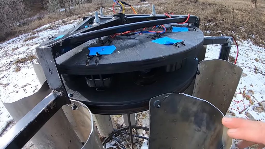
Blue painter’s tape tabs marked 1, 2 and 3 are stuck to the disc so you can see which coil belongs to which phase. Nine coils and twelve magnets is the combination this generator is built around.
Step 12 : Wiring the three phase star
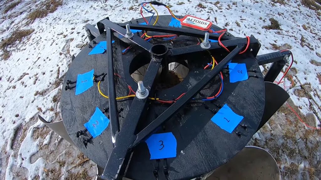
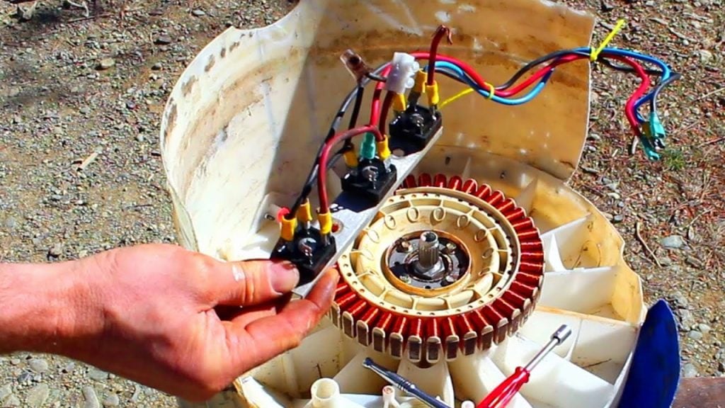
Split the nine coils into three groups of three, then wire each group in series to form one phase. Within each group, connect the first coil’s outside wire to the second coil’s inside wire, and the second coil’s outside wire to the third coil’s inside wire, which is why you marked the coil ends before taping. The third coil’s outside wire is left alone, because it is that phase’s output. Bundle the inside ends of the first coil in each of the three groups together to form a common neutral point.
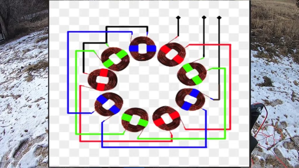
That arrangement is a star connection. It combines the three phases onto one shared neutral and leaves three output wires running to the terminals. The 120 degree displacement between the phases comes from where the three coil groups sit against the alternating magnet poles, not from the wiring itself.
Step 13 : Building the bridge rectifier
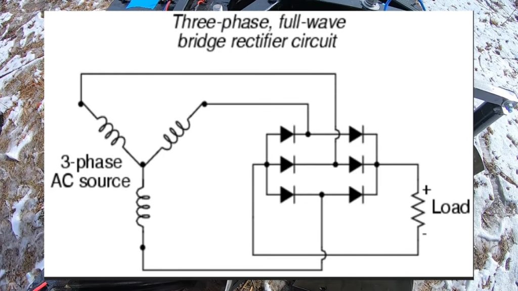
The three phase output is alternating current, so it passes through a full wave bridge rectifier made from six diodes arranged as three parallel legs of two diodes each. These are Schottky diodes bought new and sized well above the expected current, around 15 amps apiece. A 50 volt capacitor is soldered straight across the DC output to smooth it.
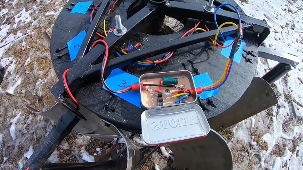
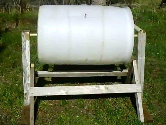
The whole circuit lives in an empty Altoids tin lined with 1/4 inch plywood so nothing shorts to the metal. It does not need to be watertight, because the generator head is covered by a bolted on cover cut from a 55 gallon drum and sees very little weather. A length of 14 gauge bonded wire carries the finished DC away from the tin.
Step 14 : The frame, fins and air gap
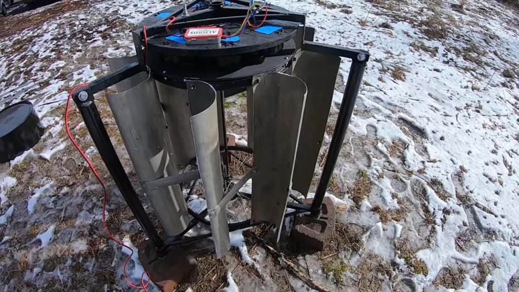
The frame is welded from just under 10 feet of 1 inch square steel tubing, with the remainder made up from 3/4 inch fence tubing already on the property. The welded joints look neater than bolted ones, though you could just as easily build the same frame out of wood instead.
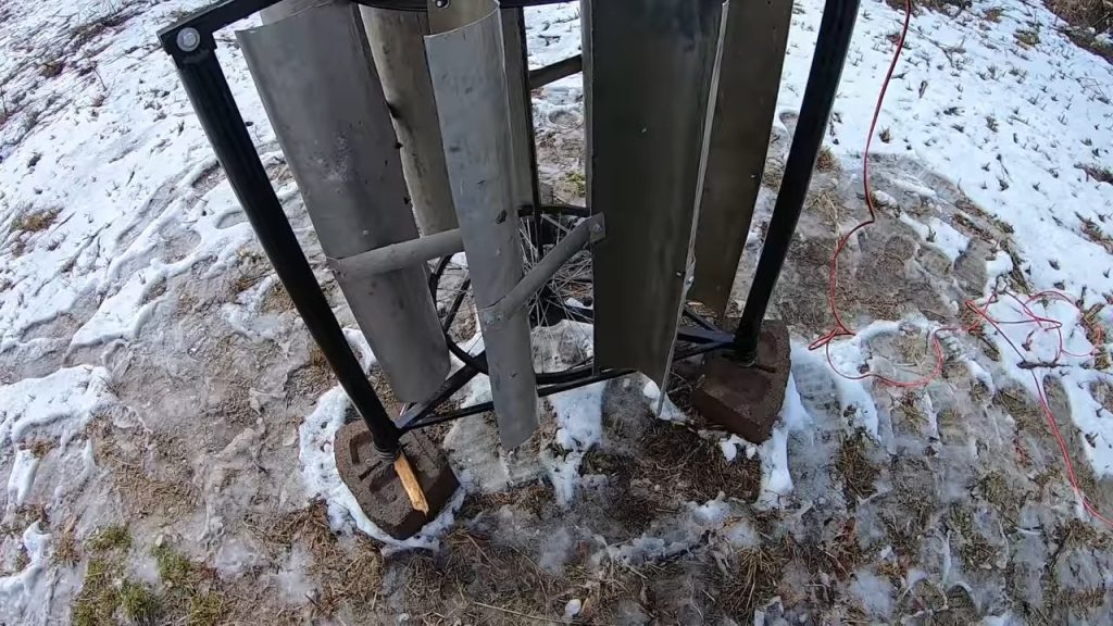
Braces and base supports keep the structure stout, because the connection from fin to rotor wants to be solid and rigid so that the energy arriving at the fins goes into pushing the magnets across the coils rather than into flexing the frame.
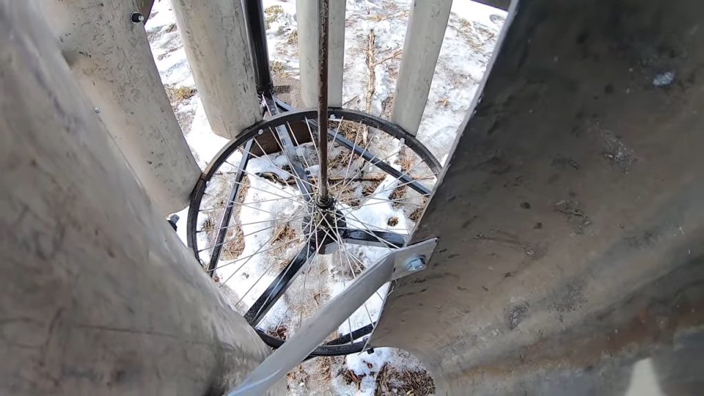
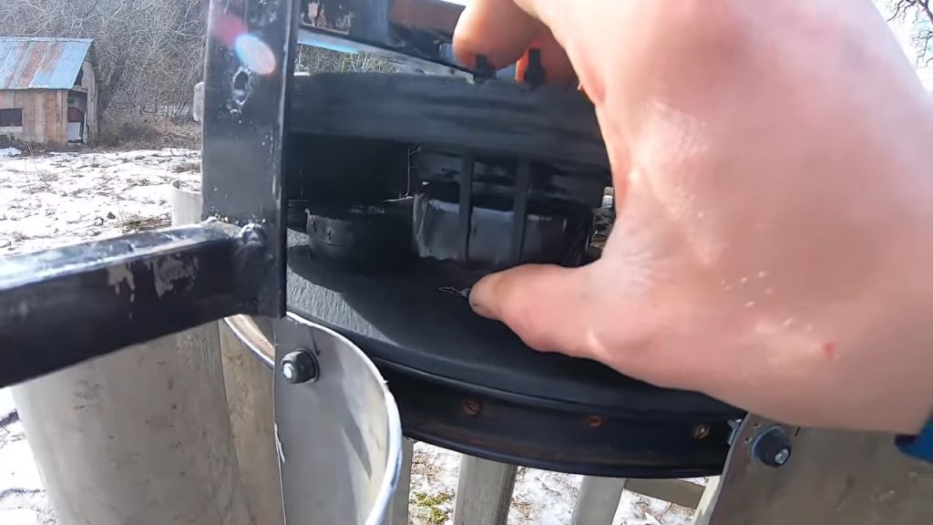
The rotor turns on two bicycle wheels taken from one child size bike, which you can usually get free by asking around. Bike wheels are made to take abuse, to live outdoors and to get wet, they are durable, and they are easy to replace. The hub is already set up to mount to a flange, and a hole is drilled in the bottom of the mounting piece. The connecting rod slides over the post ends and is retained with cotter pins. Keep the pins and the hub well lubricated.
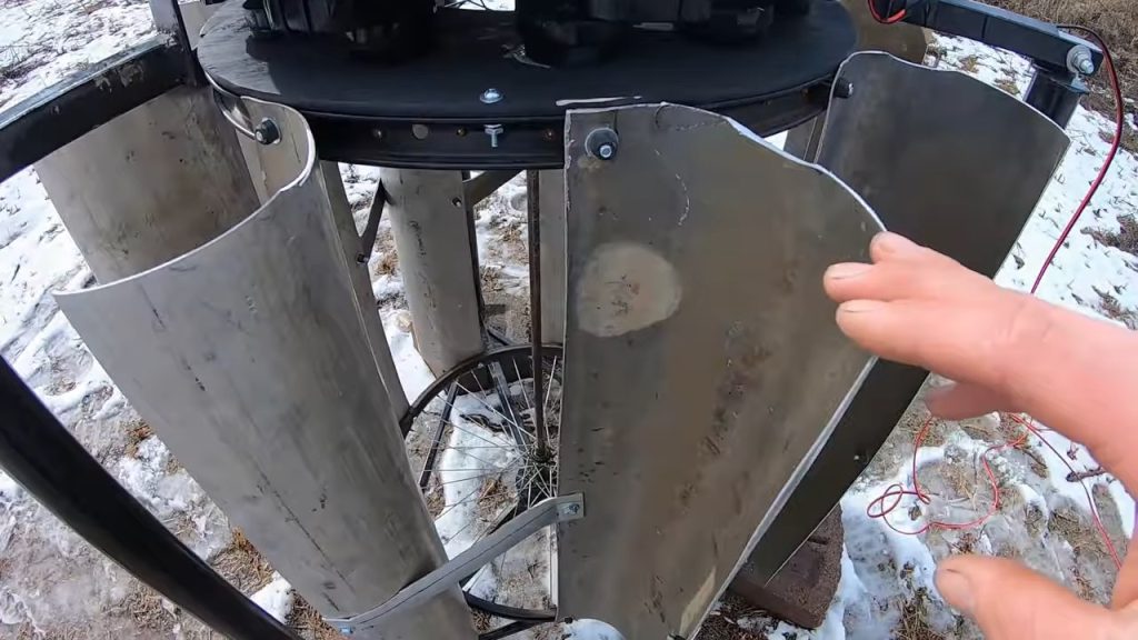
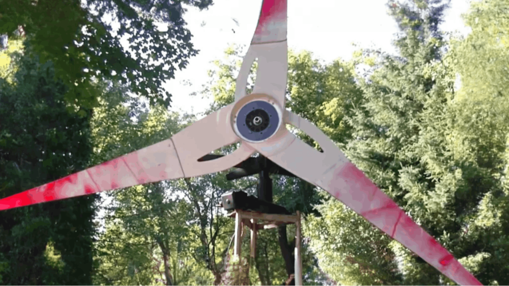
Curved vertical fins bolt to brackets on the rotor. Fin length is a compromise: the further out the fins sit, the more torque they apply against the magnets and coils, but the assembly is heavier, so chances are it will spin slower and need more wind to get moving. The stator stands over the rotor on adjustment bolts that set the air gap. Get the coils as close to the magnets as your assembly allows, since a closer gap gives the magnets more influence over the windings.
Step 15 : Testing the output
With the multimeter across the DC terminals and the rotor at rest, the capacitor holds about 2.5 volts. Spinning the rotor by hand brings the reading up to 13.8 volts, then 15.3 volts with more speed, then 15.7 volts. The meter face does not read clearly, so the figures are given here instead: the machine sits between 15 and 16 volts at a good solid moderate wind.
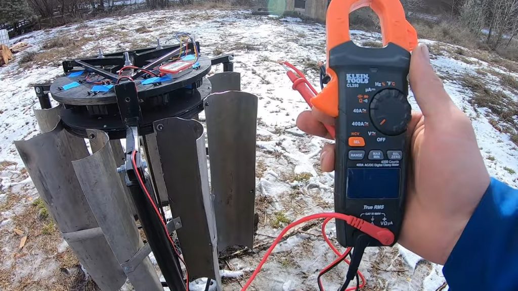
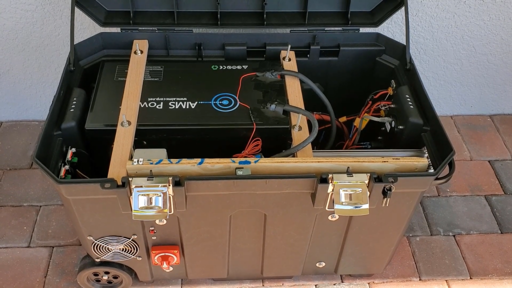
To put the generator into service, feed the DC output to a wind charge controller and the controller output to a battery. The turbine was built to work alongside a 50 watt solar panel.