The increasing demand for energy coupled with concerns over environmental sustainability has prompted the exploration of alternative power generation methods.
One such method involves the use of a water wheel powered by flowing water from a stream or creek. This project details the construction of a homemade off-grid power generation system using this technique.
The initial step in harnessing power from the water source involves constructing a small dam to collect and regulate the flow of water.
This ensures maximum efficiency of the water wheel and optimal power output. The system is designed to be sustainable, cost-effective, and reliable, providing an alternative power source for homes and small businesses located near a flowing water source.
Through the use of readily available materials and easy-to-follow instructions, this project provides an opportunity for individuals to contribute to a more sustainable future while reducing their dependence on traditional power sources.
With proper maintenance, this off-grid power generation system can provide a reliable and sustainable energy source for years to come.
STEP 1 : BUILDING THE DAM
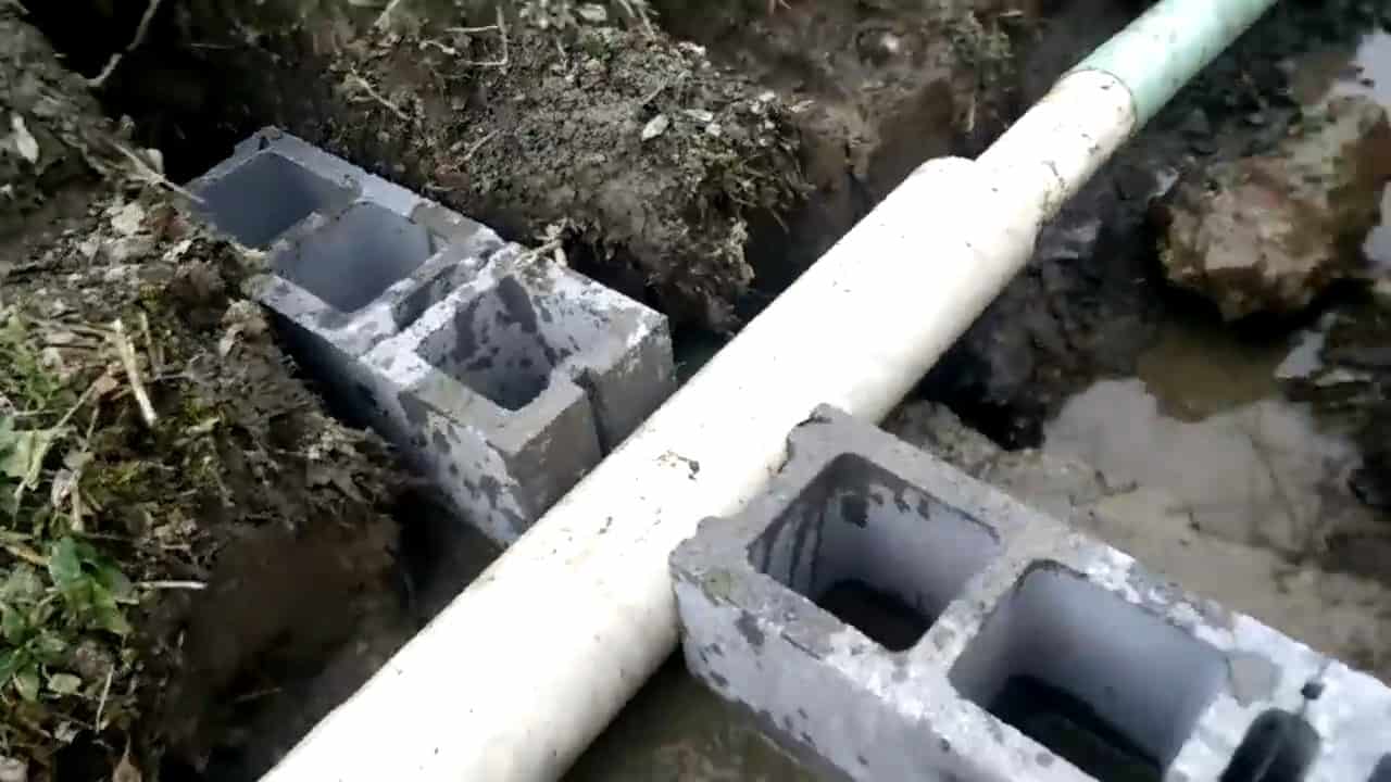
To begin with, it is crucial to divert the water using a 4 inch pipe before commencing the construction of the dam. This ensures that the work area is dry and enables a better construction process.
The construction of the dam itself involves creating a solid concrete foundation, which will serve as the base for the structure. The dam should be 42 inches in length with a 30 inch head to ensure maximum water flow for the water wheel.
On the high water side of the dam, a six inch, 36 inches long PVC drain pipe is installed. This drain pipe helps to regulate the water flow and prevent overflows, which can lead to damage and reduce the efficiency of the water wheel.
To construct the dam, four layers of hollow blocks are used along with quickrete blended mason mix to provide stability and durability.
It is essential to test the dam’s strength by gradually increasing the water level to determine the maximum height it can hold before overflowing.
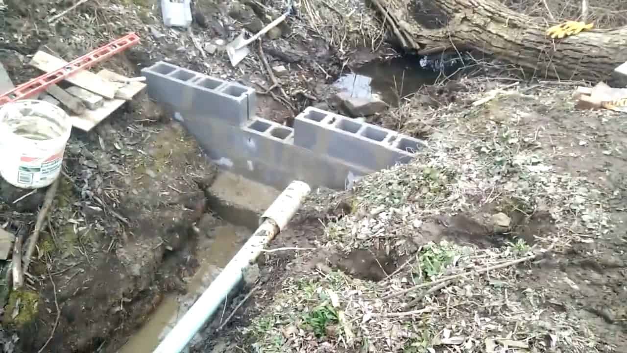
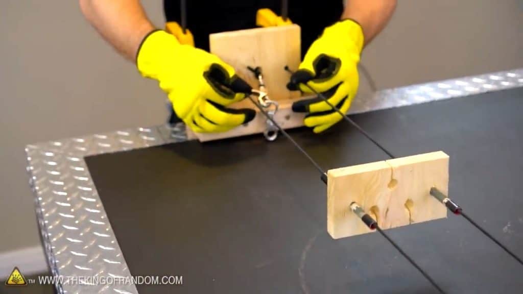
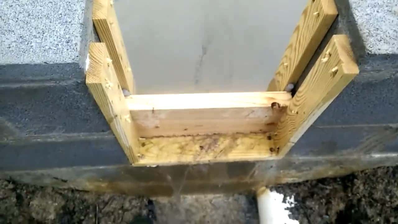
After constructing the dam structure, the next step involves installing the dam board gates, which are made of sturdy deck boards. These gates are placed in the middle of the dam and act as barriers to regulate the water flow.
To install the dam board gates, the back and front boards are spaced apart with a distance of one and three-quarters inches.
This allows the dam stop gate, which is made of plywood and measures one and a half inches, to fit snugly between the boards.
To ensure a tight seal and prevent any water from seeping through, a half-inch rubber tube is stuffed between the boards. This rubber tubing acts as a gasket, providing a watertight seal when the dam stop gate is inserted.
STEP 2 : BUILDING THE FLUME
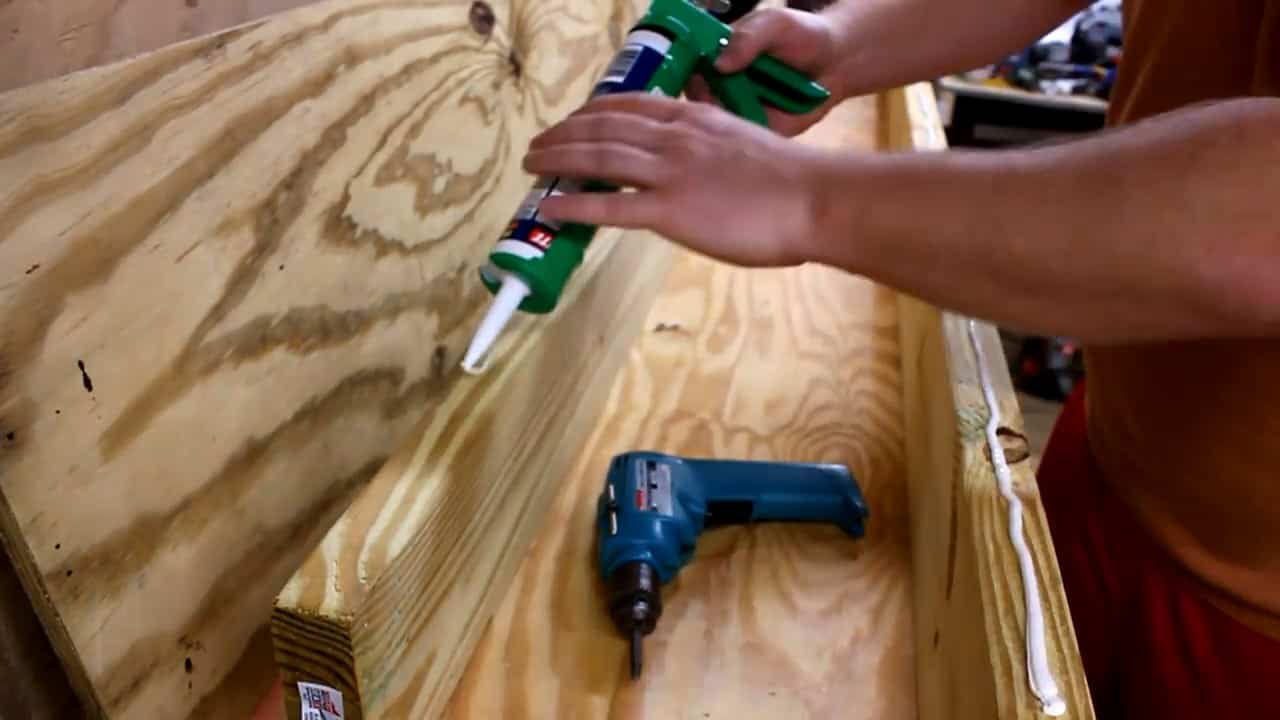
To construct the flume, a 13 and a half inch treated plywood is used as the base, along with a couple of 2×6 plywood side boards.
The plywood base and side boards are secured together using a strong adhesive sealant and exterior grade screws. It is important to ensure that the boards are tightly fastened together to prevent any water leakage.
The flume is designed to channel the water from the dam to the water wheel. It is important to take into consideration the length and angle of the flume, as well as any obstacles that may affect the flow of water.
The flume should be sloped at a consistent angle to ensure a steady flow of water to the water wheel.
To ensure stability and prevent warping of the plywood, four cross spacers are strategically placed along the flume board.
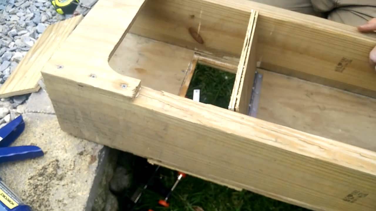
These spacers also help maintain a consistent width for the flume, which is essential for optimal water flow. In order to divert the water without the need to completely drain the dam, a small trap door is constructed in the flume near the opening.
The trap door is positioned approximately seven inches from the face of the dam and is supported by a sturdy flange on the back and a durable stainless steel hinge.
This design ensures that the trap door remains securely in place, effectively diverting water as needed.
![]()
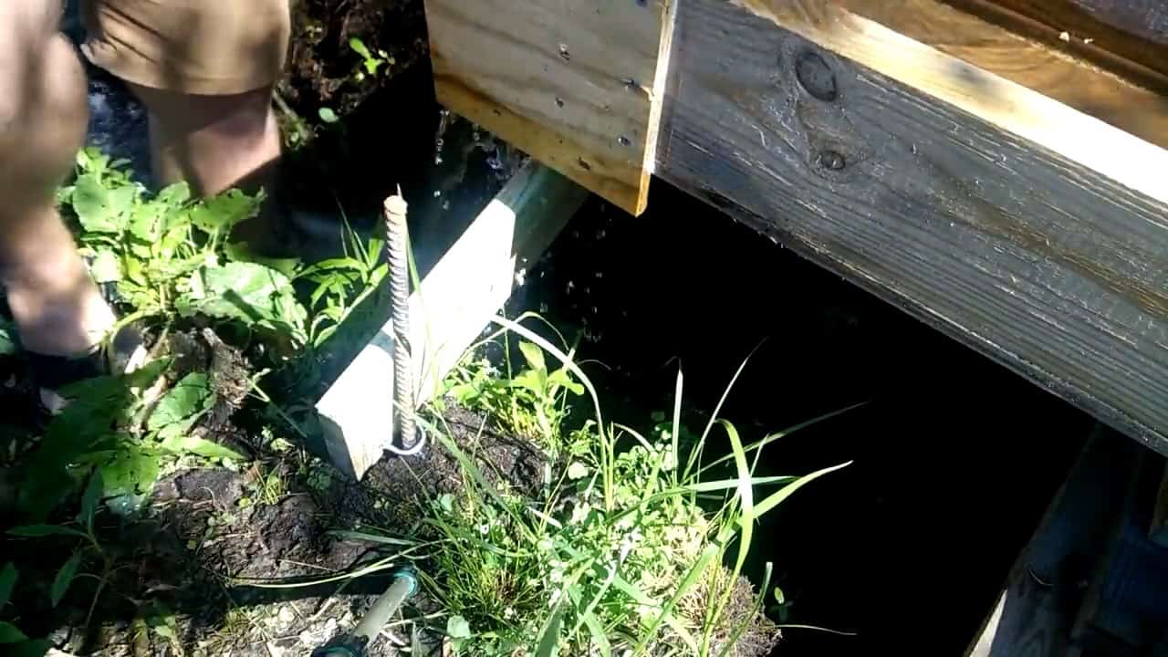
Once the flume is constructed, it is time to install it on the creek or stream. This requires attaching rebars to supporting deck boards using u-bolts and a drill bit.
The rebars provide stability to the flume and ensure that it remains securely in place.
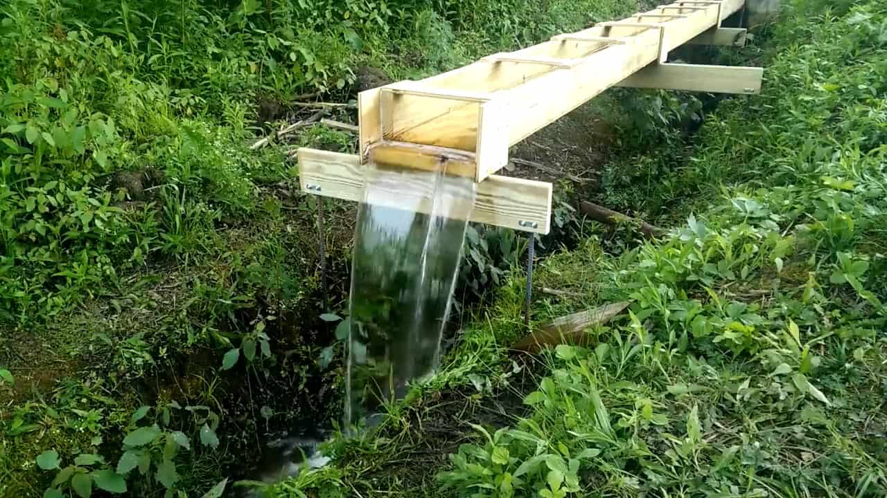
In order to extend the length of the flume, three subsequent flumes are attached to each other. To seal the gaps between the flumes, poly foam caulk rope is applied.
This ensures that there are no leaks or water loss between the different sections of the flume.
Proper installation of the flume is crucial for the efficient operation of the water wheel. It is important to ensure that the flume is level and properly supported.
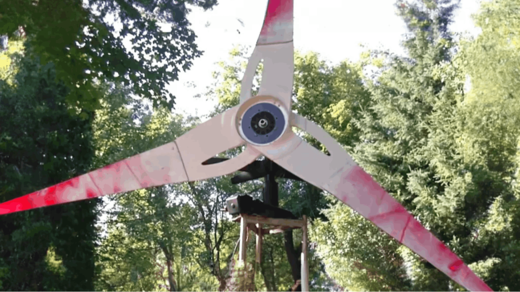
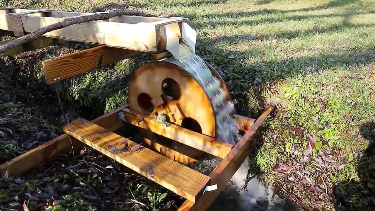
STEP 3 : MAKING THE WATER WHEEL
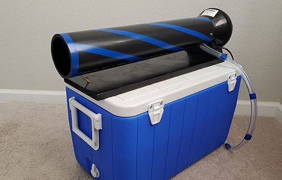
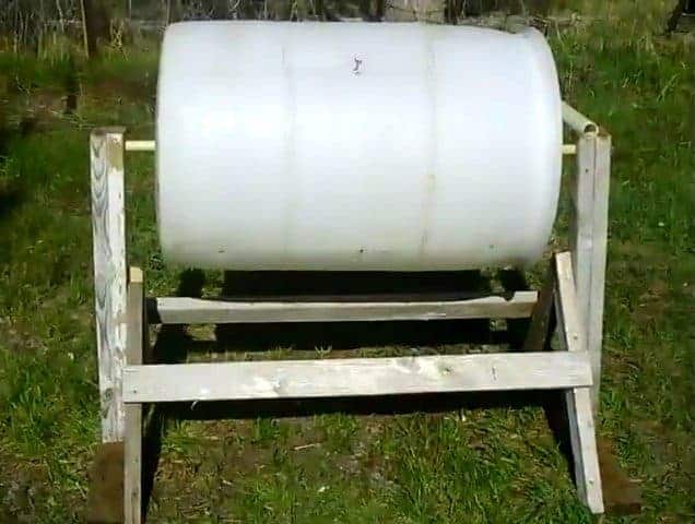
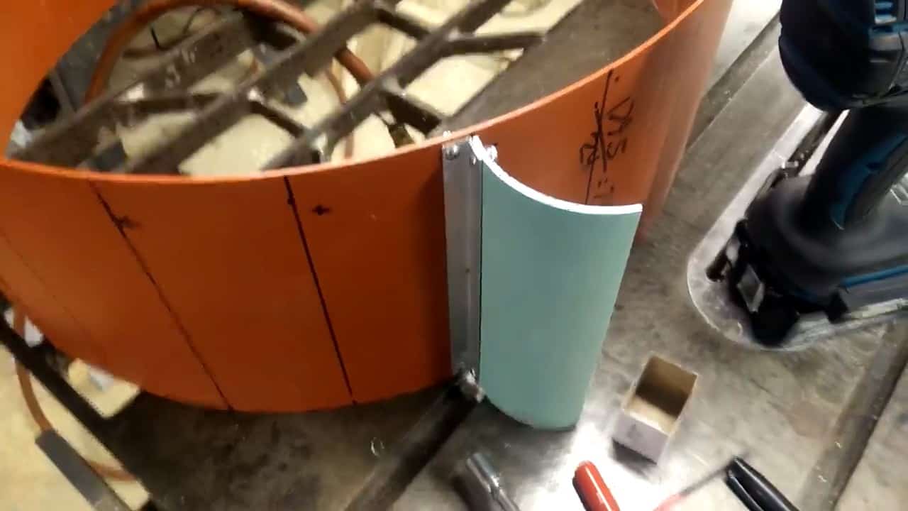
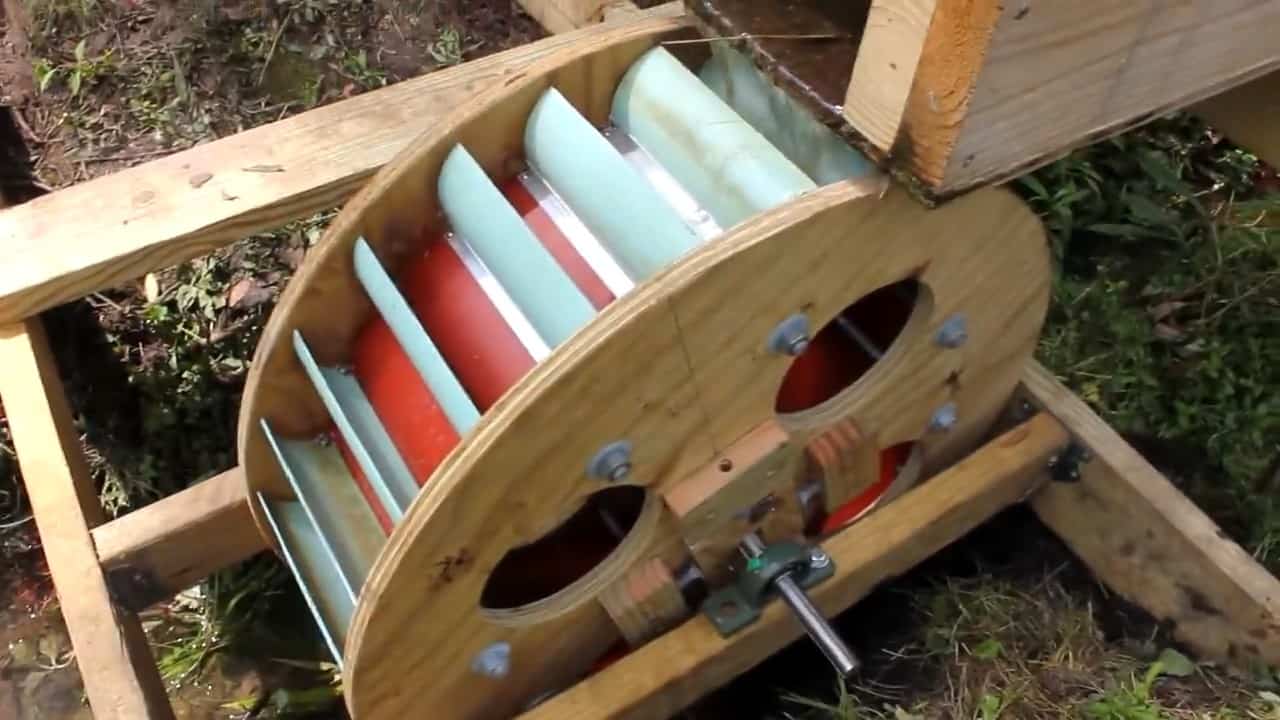
To construct the waterwheel, a section of 55-gallon HDPE drum is utilized as the main body. For the blades, 4-inch PVC drain pipe is cut into suitable lengths and curved in a manner that allows it to retain a majority of the water passing through, thus increasing its energy efficiency.
A total of 24 blades are attached to the drum using 16th by half aluminum angle pieces, ensuring a strong and stable connection.

The next step in building this homemade off-grid power generation system is to install the drive shaft and complete the waterwheel assembly.
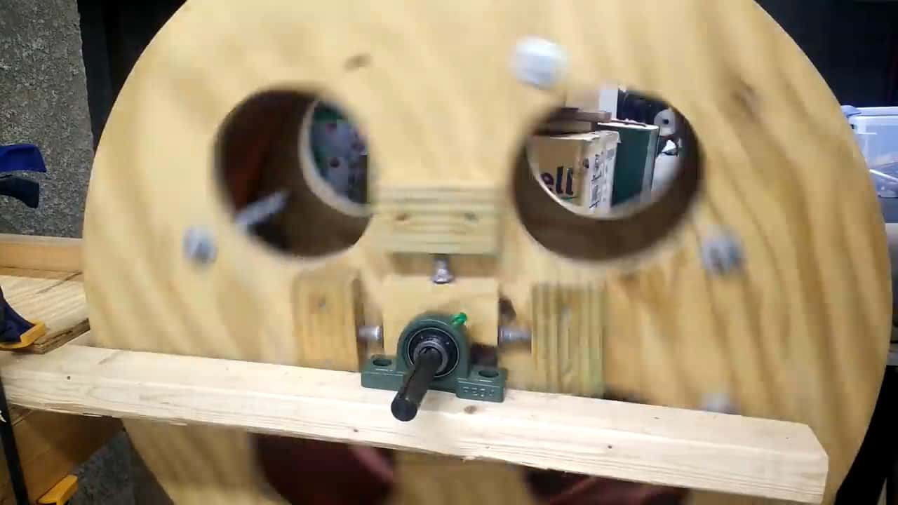
To do this, a 3/4 inch jack shaft salvaged from an old go-kart is used as the drive shaft. This jack shaft is then supported at both ends of the wheel using pillow block bearings to ensure smooth rotation.
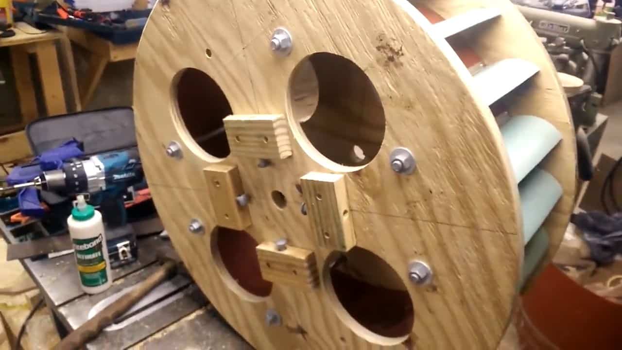
To complete the waterwheel assembly, two 28 inch circular end pieces made of plywood are bolted along both sides of the HDPE drum barrel.
This is achieved using six 10 inch long 1/2 inch by 13 carriage bolts. These end pieces serve as reinforcement for the waterwheel, providing stability and preventing any wobbling or misalignment during operation.
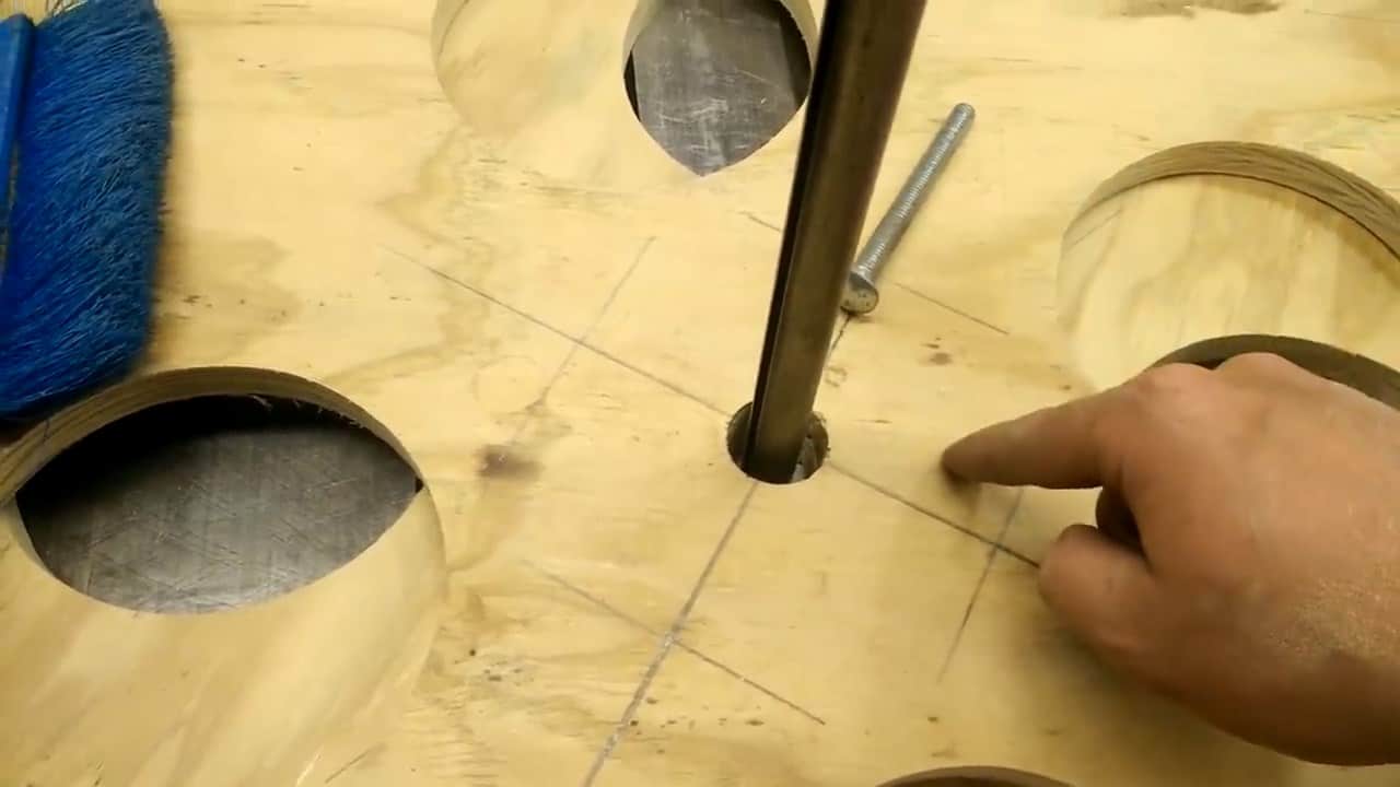
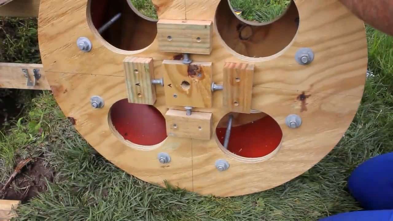
To ensure proper alignment and reduce any runout in the center shaft of the waterwheel, two square collar blocks are mounted onto the shaft.
The holes in these collar blocks are slightly larger than the diameter of the shaft to allow for adjustments. In order to further adjust and center the waterwheel, four additional blocks are placed around the center block, similar to a four jaw chuck.
These adjustment blocks are equipped with bolts that allow for precise alignment of the wheel.
STEP 4 : INSTALLING THE WATER WHEEL
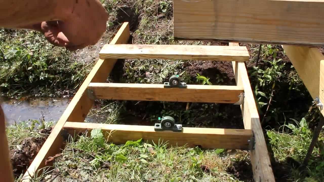
To ensure a stable and secure installation of the water wheel, a sturdy support structure is constructed using 2×4 boards. This structure is positioned at the end of the flume, where the waterwheel will be installed.
Two swivel block bearings are then mounted onto the support structure, providing a strong and durable foundation for the waterwheel.
The swivel block bearings allow for smooth rotation of the waterwheel, reducing the amount of friction and wear on the system.
The bearings are carefully selected to match the specifications of the jack shaft and other components of the waterwheel system, ensuring a precise and reliable fit.
STEP 5: CONNECTING THE MOTOR AND THE WATERWHEEL
To ensure the proper functioning of the water wheel and power generation system, it is essential to have a sturdy and adjustable mounting structure for the bearings, sprockets, and motor.
In this step, an adjustable Unistrut is used to mount these components, allowing for easy chain tension adjustments. The Unistrut is mounted vertically on top of the cross support that is under the flume.
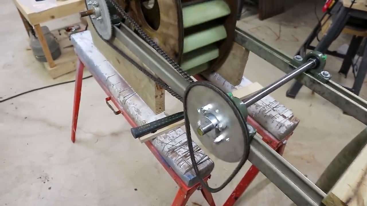
To secure the Unistrut onto the wheel, bearings and T-nuts are used on both sides. A Number 35 sprocket with 72 teeth is then mounted onto the center wheel shaft.
This sprocket will help in transferring the power from the water wheel to the generator or other mechanical devices.
By using an adjustable Unistrut, the positioning of the sprockets and motor can be fine-tuned to optimize the power output of the system.
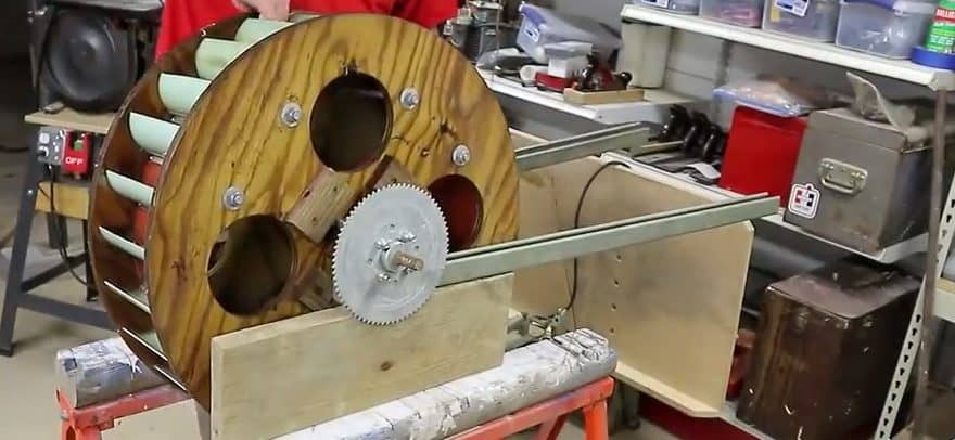
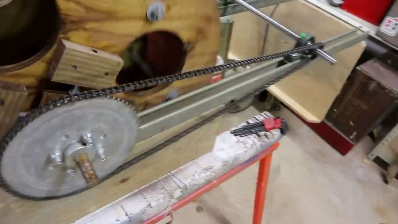
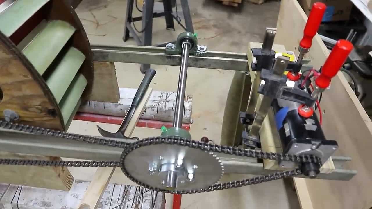
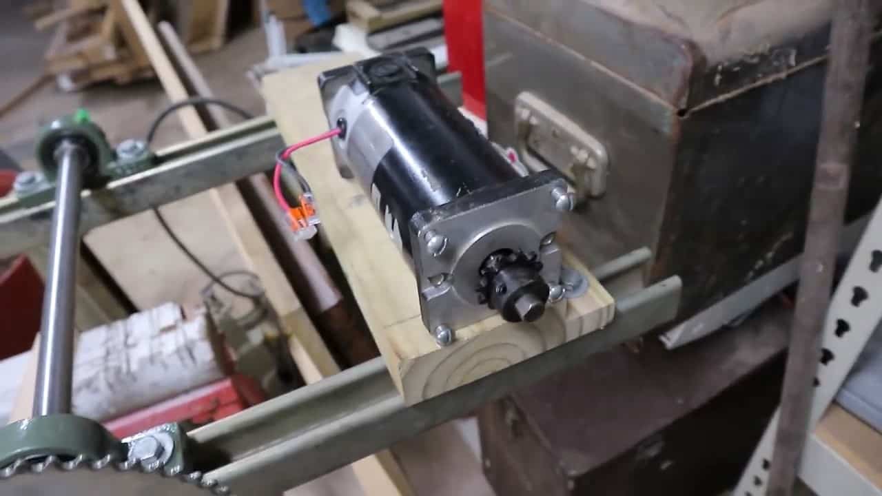
This sprocket is then connected to a half shaft with an 11 tooth sprocket using a size 35 go-kart roller chain. Finally, a Permanent Magnet Brushed DC motor mounted on a 2×4 board is connected to this shaft via another sprocket.
The gear system has a ratio of 30.86:1, providing optimal power generation from the water wheel’s rotation.
To ensure the water wheel operates efficiently, it is important to position it correctly. This is achieved by mounting the wheel onto the support board near the flume using unistruct angled brackets.
The brackets allow for adjustment of the wheel’s position to ensure the point where the water meets the wheel is exactly at the top.

STEP 6: CONNECTING THE CHARGING SYSTEM
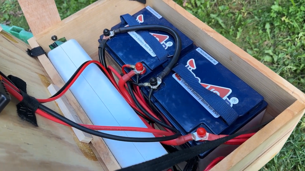
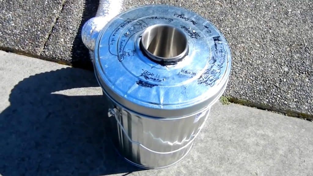
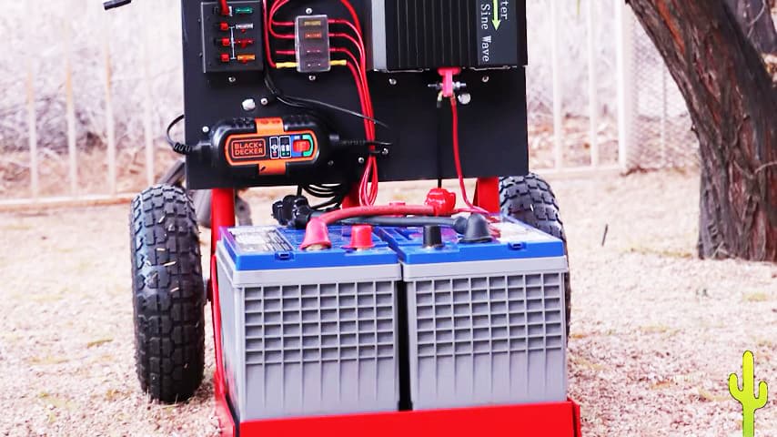
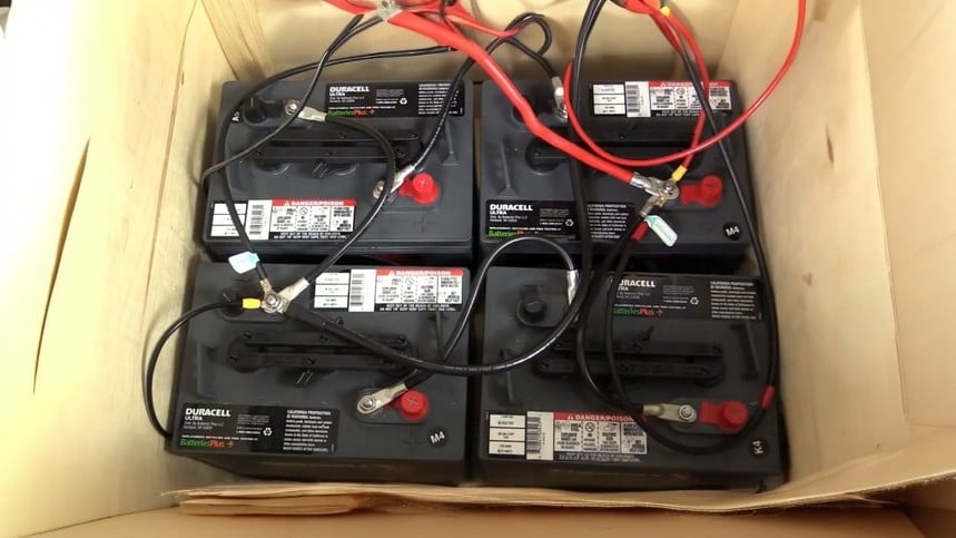
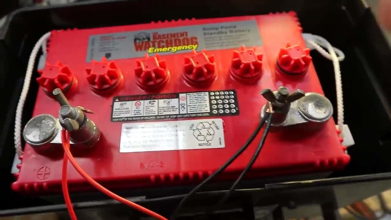
The charging system of the water wheel project is a crucial aspect that helps generate electrical energy. It involves the use of a few components such as a 12V DC standby battery, a Maximum Power Point Tracking (MPPT) charge controller, and a 300W sine wave inverter.
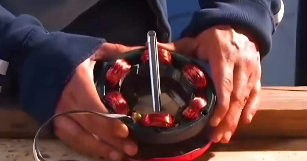
The DC motor of the water wheel is connected to the charge controller, which regulates the power generated by the motor to optimize its efficiency.
The charge controller is responsible for ensuring that the battery is charged properly and is not overcharged, which could damage the battery. It is also connected to the 12V DC standby battery, which acts as a backup power source in case of power outages or during periods of low water flow.
Furthermore, the MPPT charge controller maximizes the energy harvested from the water wheel by adjusting the electrical load to match the motor’s output, thus increasing the overall efficiency of the system.
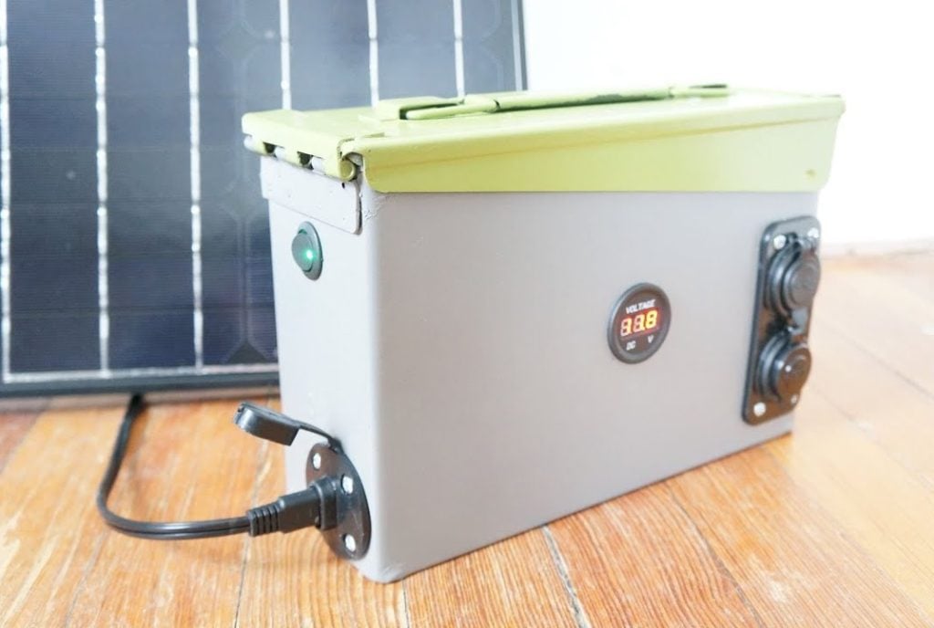
Finally, the 300W sine wave inverter is used to convert the DC voltage from the battery to AC voltage.
Once the battery is charged, the inverter is used to convert the 12V DC power from the battery into 120V AC power, which can be used to power a load.
To ensure the safety of the system, a fuse connection is installed between the components, which protects against overloading and short circuits.
All of these components are mounted onto a temporary wooden board for easy portability and maintenance.
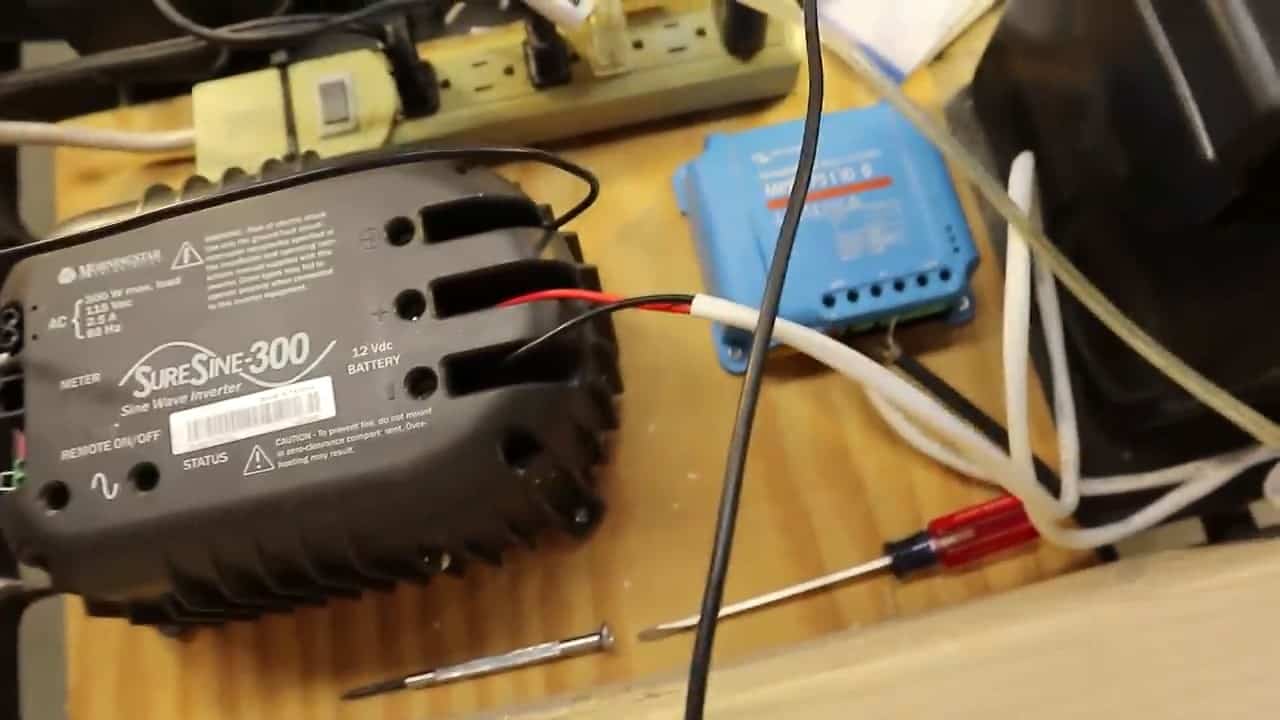
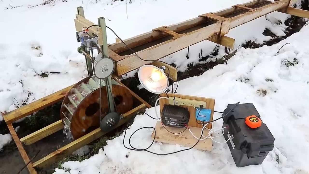
Image Credits : Joe Malovich